Connector To Facilitate Lifting Of Wear Parts

a technology of wear parts and connectors, which is applied in the direction of transportation and packaging, manufacturing tools, hoisting equipment, etc., can solve the problems of wear parts that cannot be easily lifted, wear parts that are heavy and difficult to connect, and the wear parts are heavy and difficult to lift, so as to facilitate the connection of a load, facilitate the installation and removal of wear parts, and maneuver the wear parts quickly and safely.

Inactive Publication Date: 2015-01-15
ESCO GRP LLC
View PDF45 Cites 46 Cited by
  • Summary
  • Abstract
  • Description
  • Claims
  • Application Information

AI Technical Summary

Benefits of technology

[0006]The present invention pertains to a connector to facilitate connecting of a load to a lifting device. With the present construction, the connector allows the installer to utilize various approved forms of rigging for maneuvering the wear part quickly and safely without complex rigging arrangements that require chains, straps, or other mechanisms to go under the worn wear parts. The orientation of the wear part does not dictate the safety of the removal environment, the connector allows the wear part to be installed and removed safely in any convenient orientation.

Problems solved by technology

During use, the wear parts typically encounter heavy loading and highly abrasive conditions.
These wear parts are heavy and cannot be easily lifted.
As the wear parts contact the material to be excavated the integral lifting eyes are worn away leaving no way to gain an attachment point on the worn wear part.
The uncontrolled falling of the wear part and the use of a hammer subject the operators to risks.
Moreover, the operators are still left with needing to move the wear parts from the ground to a discard pile or bin.
However, during removal, the installer can still be in potential risk if the rigging arrangements are unsecure and slip or create pinch points.
Additionally rigging arrangements that require chains, straps, or other mechanisms to go under the worn wear parts can be problematic when rigging is removed.
This is not desirable because mobile welding equipment is needed at the machine site.
Welding on site is prohibited at many mine sites as welding imposes a risk of injury.
In addition, wear parts tend to be composed of very hard steel which requires a careful and time consuming process to achieve a high quality weld.
If there is a poor weld the lifting eye may be separated from the wear part causing uncontrolled movement of the wear part.
These kind of removal requirements increase the amount of downtime required to replace wear parts and decreases productivity.

Method used


Image

  • Connector To Facilitate Lifting Of Wear Parts
  • Connector To Facilitate Lifting Of Wear Parts
  • Connector To Facilitate Lifting Of Wear Parts

Examples


Embodiment Construction

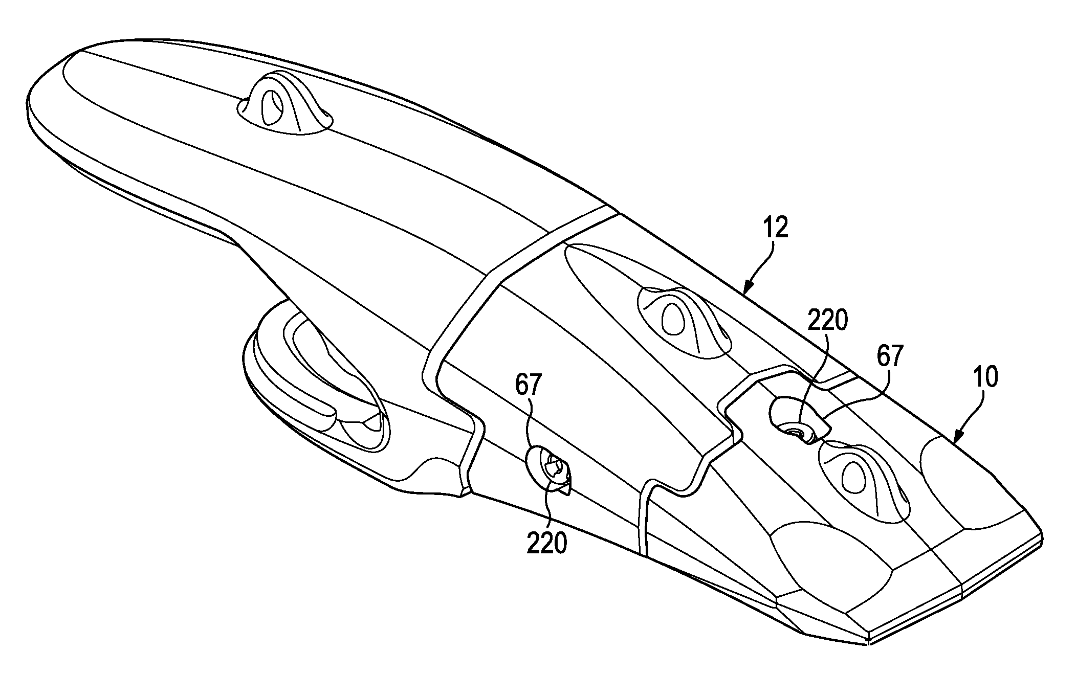
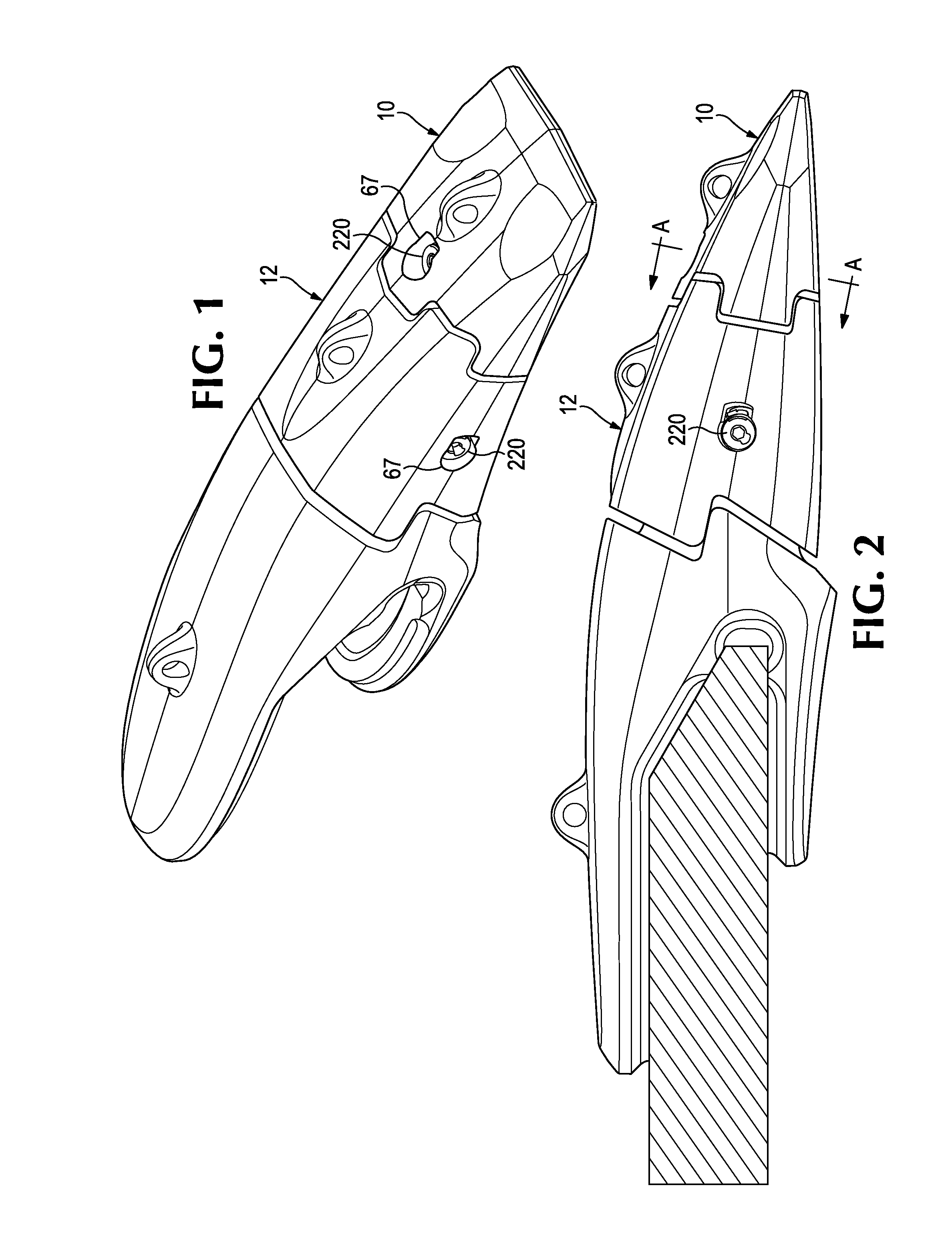
[0048]The present invention pertains to a connector to facilitate the lifting of heavy parts (such as wear parts) for earthmoving equipment by a lifting device. The lifting device may be, for example, a hoist, a crane, a robot, or other known lifting devices used to lift wear parts. The inventive aspects of the present invention are described in this application in relation to a lifting eye for use with a worn wear part used for earth working equipment. Further, in this application, relative terms are at times used, such as front, rear, up, down, horizontal, vertical, etc., for ease of the description. Nevertheless, these terms are not considered absolute; the orientation of a lifting eye can change considerably depending on the part to be lifted. These relative terms should be understood with reference to the orientation of connector 320 as illustrated in FIG. 5 unless otherwise stated. In all figures, like components use similar numbering.

[0049]In accordance with a first embodimen...


PUM

PropertyMeasurementUnit
movementaaaaaaaaaa
lengthaaaaaaaaaa
compressibleaaaaaaaaaa

Abstract

A lifting connector to facilitate the lifting of wear parts used on earthmoving equipment is mechanically secured to a hole in the wear part. The wear part has a latching formation to maintain the head of the connector in a preferred orientation so that it is in the proper service position for connecting the lifting connector to a lifting device. The wear part can be safely maneuvered onto and off of the earthmoving equipment while secured to the lifting device.

Description

RELATED APPLICATION[0001]This application claims priority benefits to U.S. Provisional Patent Application No. 61 / 844,795 filed Jul. 10, 2013 and entitled “Connector to Facilitate Lifting of Wear Parts,” which is incorporated herein by reference in its entirety.FIELD OF THE INVENTION[0002]The present invention pertains to a connector to facilitate the lifting of heavy loads, and in particular wear parts for earthmoving equipment.BACKGROUND OF THE INVENTION[0003]In mining and construction, wear parts (e.g., teeth, shrouds, and blades) are commonly provided along the digging edge of excavating equipment such as buckets for dragline machines, cable shovels, face shovels, hydraulic excavators, graders, dozers, and the like. The wear parts protect the underlying equipment from undue wear and, in some cases, also perform other functions such as breaking up the ground ahead of the digging edge. During use, the wear parts typically encounter heavy loading and highly abrasive conditions. As a...

Claims


Application Information

Patent Timeline
Patent Type & Authority Applications(United States)
IPC IPC(8): B66C1/66E02F9/28
CPCE02F9/2891E02F9/2883Y10T29/49764Y10T29/49947Y10T29/49815B66C1/66E02F9/28
Inventor ZENIER, SCOTTCARPENTER, CHRISTOPHER M.STANGELAND, KEVIN S.
Owner ESCO GRP LLC
Why Eureka
Try Eureka