Turbine blade with cooling arrangement

a cooling arrangement and turbine blade technology, applied in the direction of blade accessories, engine fuctions, machines/engines, etc., can solve the problems of limited maximum operating temperature and additional energy consumption of the turbine engine, and achieve the effect of reducing the amount of cooling fluid required for desired heat removal, improving cooling arrangement, and improving cooling efficiency

Inactive Publication Date: 2017-07-11
SIEMENS AG
View PDF14 Cites 0 Cited by
  • Summary
  • Abstract
  • Description
  • Claims
  • Application Information

AI Technical Summary

Benefits of technology

[0010]Accordingly, an object of the present invention is to provide a turbine blade with an improved cooling arrangement such that cooling efficiency is increased, and thereby, an amount of cooling fluid required for desired heat removal is reduced.
[0012]An underlying idea of the present invention is to provide a turbine blade with a cooling arrangement such that cooling fluid supplied to the turbine blade is initially used for impingement cooling of airfoil walls in a mid-chord section thereof and subsequently, is directed back towards an interior region of the turbine blade through an intermeshing arrangement of fluid channels. In the interior region, the cooling fluid is used for convective cooling, and finally, is discharged therefrom through multiple film-cooling holes. Therefore, the cooling arrangement of the present invention is configured for efficiently exploiting cooling (or heat absorbing) capacity of the cooling fluid.
[0014]Accordingly, the turbine blade of the present invention is provided with an improved cooling arrangement such that cooling efficiency is increased. Thus, an amount of cooling fluid required for desired heat removal is advantageously reduced.

Problems solved by technology

However, the maximum operating temperature is limited by the thermal strength of various internal components, and in particular, turbine blades located in the downstream turbine.
As mentioned earlier, the cooling fluid supplied to the cooling arrangement in a turbine blade is bled from the upstream compressor, and thus, represents additional energy consumption in the turbine engine.

Method used


Image

  • Turbine blade with cooling arrangement
  • Turbine blade with cooling arrangement
  • Turbine blade with cooling arrangement

Examples


Embodiment Construction

[0020]Various embodiments are described with reference to the drawings, wherein like reference numerals are used to refer to like elements throughout. In the following description, for purpose of explanation, numerous specific details are set forth in order to provide a thorough understanding of one or more embodiments. It may be evident that such embodiments may be practiced without these specific details.

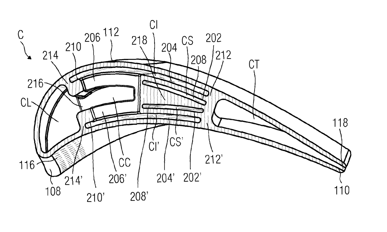
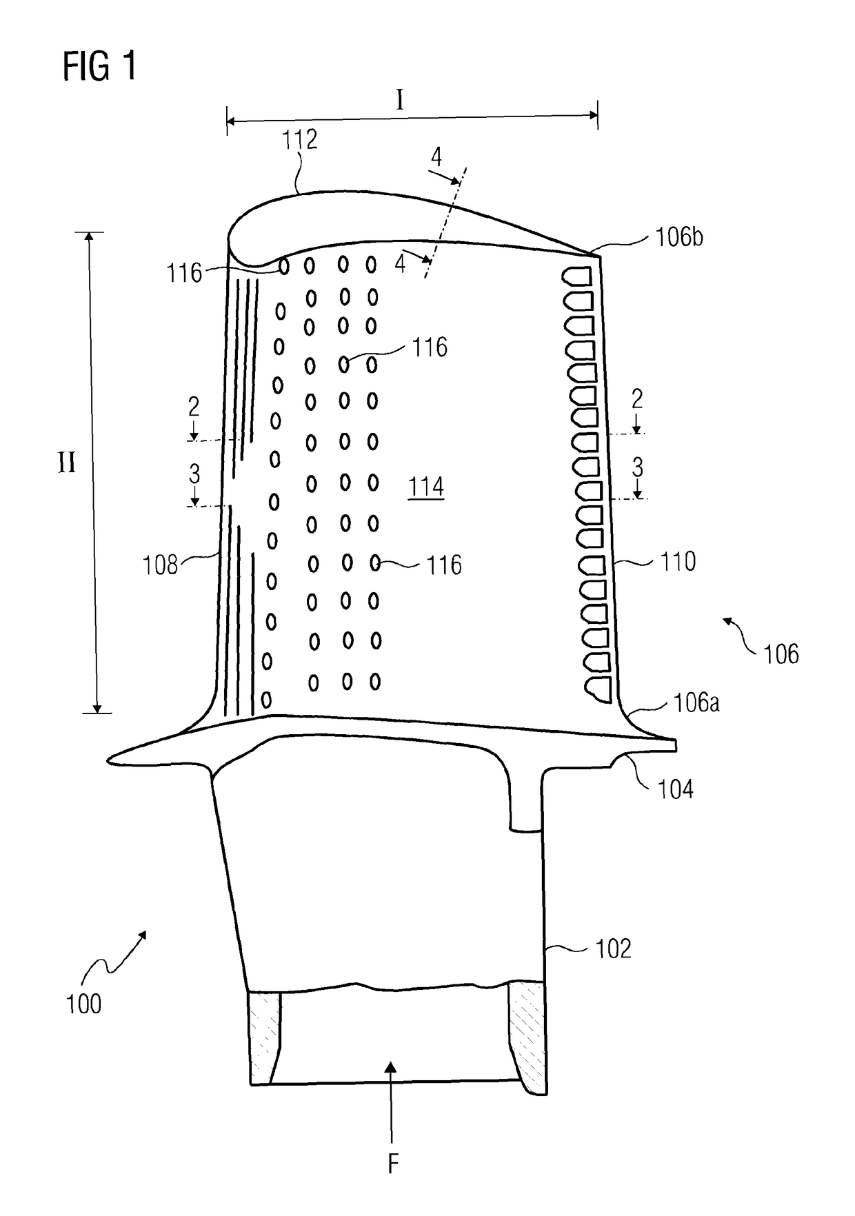
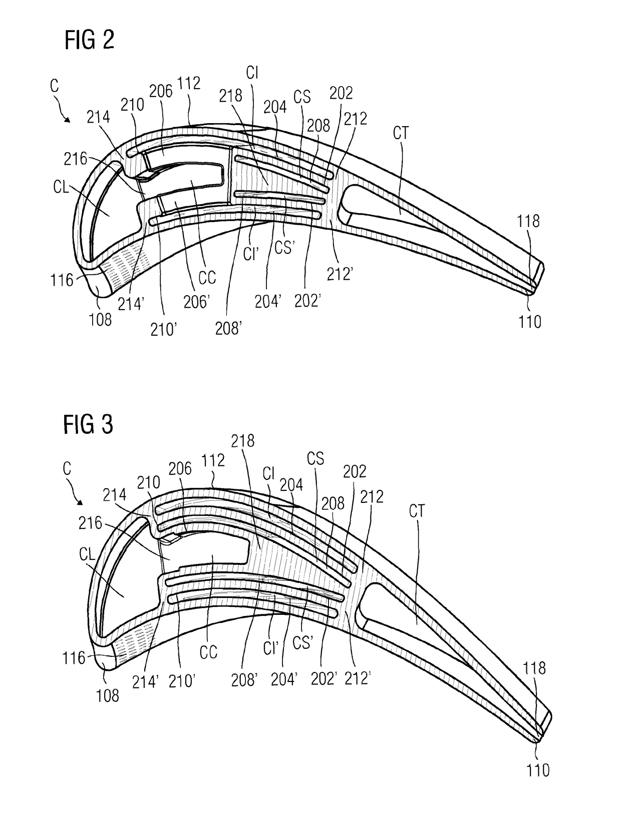
[0021]Referring to FIG. 1, a side view of a turbine blade 100 is depicted in accordance with an embodiment of the present invention.

[0022]The turbine blade 100 typically includes three sections, namely a blade root 102, a blade platform 104, and an airfoil 106. The turbine blade 100, as used to herein, refers to rotor blades as well as stator blades (also referred to as stator vanes). The turbine blade 100 is mounted on a rotor or a stator with the help of the blade root 102 and the platform 104 in a well-known manner.

[0023]The airfoil 106 includes a leading edge 108 and a trailin...


PUM


Abstract

A turbine blade with a cooling arrangement is provided. The turbine blade includes at least one supply chamber and at least one impingement cavity. The supply chamber includes multiple impingement channels configured to direct a cooling fluid from within the supply chamber to the impingement cavity. The supply chamber also includes one or more collector channels such that the cooling fluid from the impingement cavity is directed to a collector cavity within the turbine blade.

Description

CROSS REFERENCE TO RELATED APPLICATIONS[0001]This application is the U.S. National Stage of International Application No. PCT / EP2013 / 072377 filed Oct. 25, 2013, and claims the benefit thereof. The International Application claims the benefit of European Application No. EP12192893 filed Nov. 16, 2012. All of the applications are incorporated by reference herein in their entirety.FIELD OF INVENTION[0002]The present invention generally relates to turbine blades. More specifically, the present invention relates to a hollow turbine blade provided with a cooling arrangement.BACKGROUND OF INVENTION[0003]In a typical turbine engine, also known as a gas turbine or a combustion turbine, an upstream compressor is coupled to a downstream turbine, and a combustion chamber is located in-between. A gas stream enters the turbine engine from the compressor end, and is highly pressurized in the upstream compressor; the compressed gas stream subsequently enters the combustion chamber at a high velocit...

Claims


Application Information

Patent Timeline
Patent Type & Authority Patents(United States)
IPC IPC(8): F01D5/18
CPCF01D5/187F01D5/186F05D2220/32F05D2260/201
Inventor SZIJARTO, JANOSUTRIAINEN, ESA
Owner SIEMENS AG
Why Eureka
Try Eureka