Camera assembly having a cooling arrangement

a technology of cooling arrangement and camera assembly, which is applied in the field of camera assembly, can solve the problems of increasing the noise generated by the system, increasing the complexity of installation or design, and a design that could be perceived as too bulky, so as to improve the cooling arrangement, efficient cooling, and efficient transfer

Active Publication Date: 2021-01-05
AXIS
View PDF22 Cites 0 Cited by
  • Summary
  • Abstract
  • Description
  • Claims
  • Application Information

AI Technical Summary

Benefits of technology

[0006]According to a first aspect, a camera assembly comprising an improved cooling arrangement is provided. The camera assembly has a housing, a transparent dome, and it is configured to receive at least one camera head arranged in the housing, inside the transparent dome. The housing comprises a cooling arrangement having a heat dissipation portion arranged within the housing and extending through the dome, wherein the heat dissipation portion is made from a material configured to transfer heat efficiently, and wherein the cooling arrangement comprises a channel for airflow. Capturing the generated heat inside the camera assembly and efficiently transferring it to an airflow leading out from the assembly enables an efficient cooling and an increased flexibility in the design of the assembly. It also enables for the heat dissipation portion to be a structural part of the assembly, and in that way the number of components may be minimized.
[0008]It is preferred that the heat dissipation portion, in one or several embodiments, extends to a chassis of the housing, to enable, e.g., a rigid construction, beneficial heat conduction properties and an adequate seal to the camera compartment.
[0010]For the same purpose, the chassis may be made from a material configured to transfer heat efficiently.
[0011]To further improve the cooling performance, the heat dissipation portion may comprise a fitting for a processing unit of the camera assembly. In this way the processing unit may be in direct contact with the very component used for dissipating the generated heat.
[0012]In one or more embodiments, a fan may arranged in the heat dissipation portion in order to enhance the airflow. The fan is preferably powered directly from a power unit of the camera assembly, yet another power source may be utilized as well. The fan may be used to enhance the convective flow being generated by the heated air, yet it may also be used to reverse the direction of the air flow. This may be preferential in some applications where an airflow in the vicinity of the dome is not desired.

Problems solved by technology

Excessive heat is a feature that is to be avoided when operating imaging sensors, e.g. CMOS sensors, since it will result in an increase in the noise generated by the system.
Thermal noise will always affect the image in a detrimental way, yet it becomes increasingly negative as the overall signal decreases, e.g. during imaging in low-light situations.
Several of the suggested actions result in an increased complexity during installation or a design that could be perceived as too bulky in some situations.

Method used


Image

  • Camera assembly having a cooling arrangement
  • Camera assembly having a cooling arrangement

Examples


Embodiment Construction

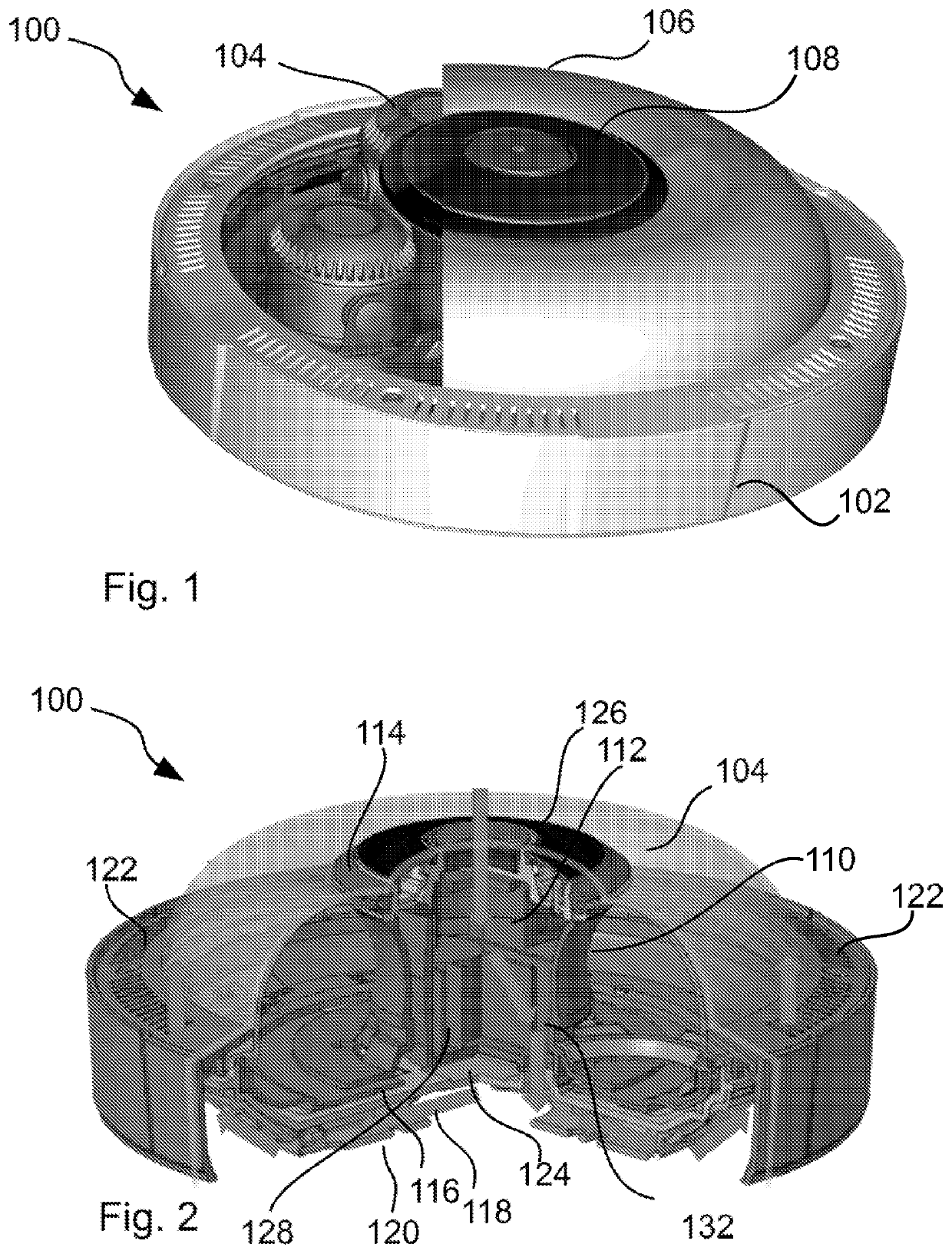
[0023]A camera assembly 100, in which the present teachings may be embodied, is illustrated in the perspective view of FIG. 1. The camera assembly 100 comprises a housing 102, one or more camera heads 104, and a transparent dome 106. A similar version of such a camera assembly is disclosed in EP2887328, by the present applicant.

[0024]Part of the transparent dome 106 has been cutaway so some camera heads 104 are clearly visible. A central part 108 of the assembly may comprise connectors, control units etc. (not shown), for receiving, processing and forwarding the result of the imaging effected by the camera heads 104. The central part 108 will in this embodiment comprise the cooling arrangement, or at least a portion thereof, and we will return to that. First, two things may be noted to increase the understanding of the present illustrated camera assembly 100; each of the individually mentioned portions may in fact comprise several parts, e.g. the “housing 102” may comprise a base, a...


PUM


Abstract

A camera assembly includes a housing and a transparent dome, and it is configured to receive at least one camera head arranged in the housing, inside the transparent dome. The housing comprises a cooling arrangement having a heat dissipation portion arranged within the housing and extending through the dome, and the heat dissipation portion is made from a material configured to transfer heat efficiently. Furthermore, the cooling arrangement comprises a channel for airflow.

Description

TECHNICAL FIELD[0001]The present invention relates to a camera assembly and in particular a camera assembly having a cooling arrangement.TECHNICAL BACKGROUND[0002]Within the context of surveillance cameras use is often made of standalone units comprising one or more camera heads and associated electronics. Surveillance cameras may be arranged in exposed environments in terms of water, moisture, dust, etc., and it may also be of interest to protect camera heads from being affected detrimentally by physical actions, such as criminal damage (vandalism) or from impacts of a more accidental nature. For these reasons it is generally preferred to arrange the camera head or camera heads within a protective housing. Such protective housing typically comprises a chassis in which the electronics and camera heads are arranged, and transparent portion, such as a dome or window. The purpose of the transparent portion is of course to allow transmission of radiation of interest for sensors of the c...

Claims


Application Information

Patent Timeline
Patent Type & Authority Patents(United States)
IPC IPC(8): H04N5/225G03B17/55G09G5/00
CPCH04N5/2252G03B17/55G09G5/00H04N5/2251H04N5/2258H04N23/45H04N23/50H04N23/51G03B17/02G03B2217/002
Inventor COLLRYD, STEFANHERTZMAN, ANDREASBOKVIST, MALTE
Owner AXIS
Why Eureka
Try Eureka