Electric arc furnace

A technology of electric arc furnace and refractory lining, which is applied in the field of electric arc furnace, can solve the problems of difficulty in installation and maintenance of refractory lining, reduction of lining structural strength, etc.

Inactive Publication Date: 2008-02-20
PAUL WURTH SA
View PDF4 Cites 0 Cited by
  • Summary
  • Abstract
  • Description
  • Claims
  • Application Information

AI Technical Summary

Problems solved by technology

However, in this method, the structural strength of the lining is also reduced, and the installation and maintenance of the refractory lining becomes more difficult

Method used


Image

  • Electric arc furnace
  • Electric arc furnace
  • Electric arc furnace

Examples


Embodiment Construction

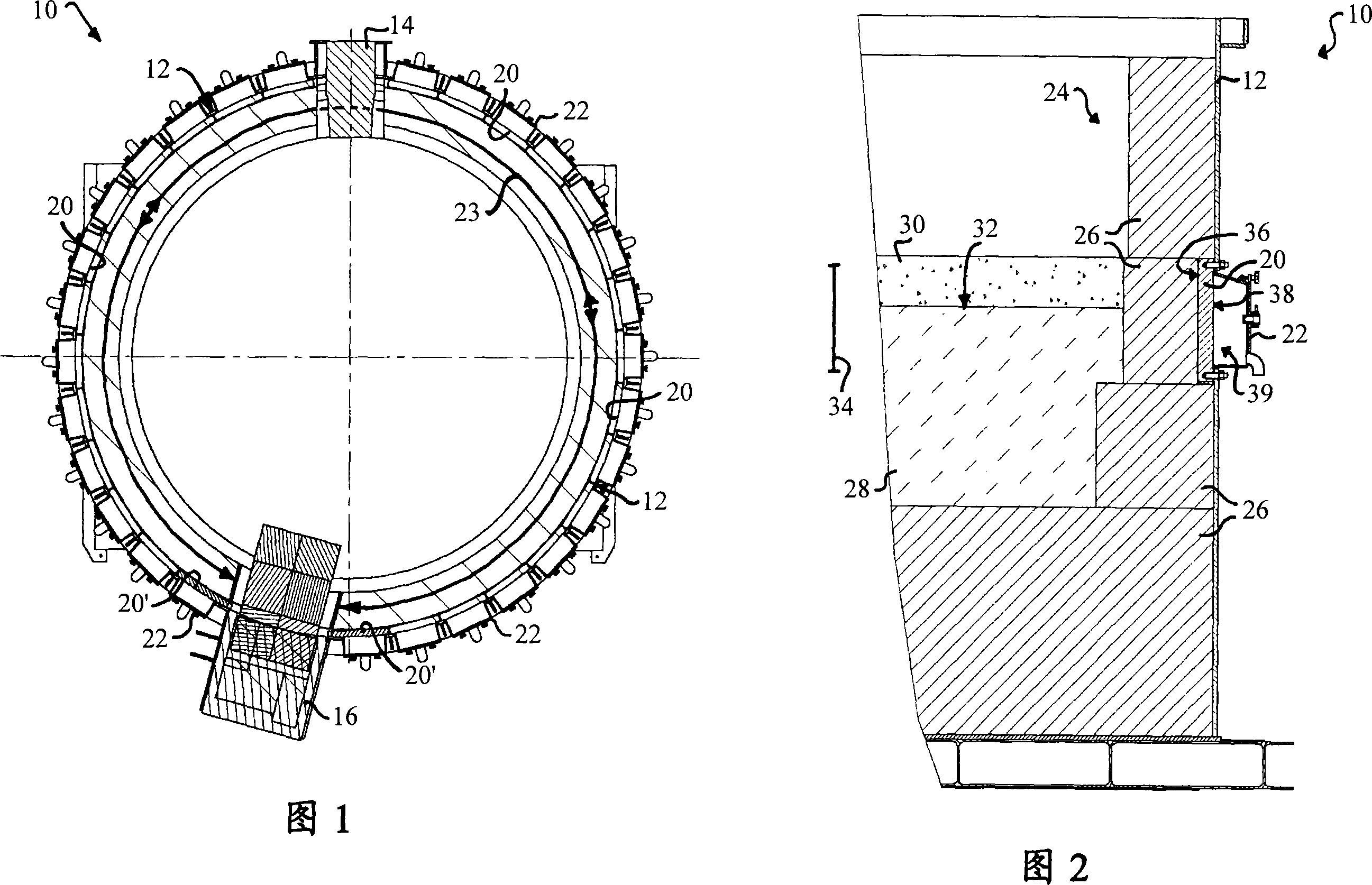
[0027] FIG. 1 shows a horizontal section through an electric arc furnace, which is generally indicated by the reference numeral 10 . The cylindrical outer furnace shell 12, made of welded steel plates, is internally lined with refractory material. The section in Figure 1 is through a taphole 14 for discharging molten metal and also shows a slag door 16 for discharging slag formed on top of the pool of molten metal during operation.

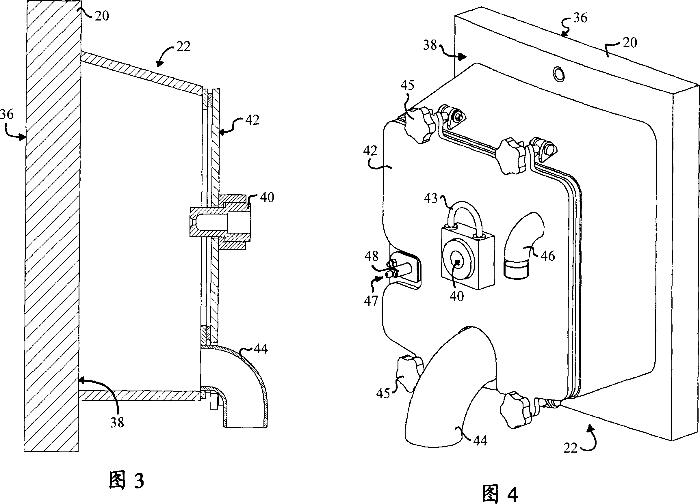
[0028] As shown in FIG. 1 , a plurality of copper slabs (copper slabs) 20 , 20 ′ are installed inside the housing 12 . Each copper plate 20, 20' is provided with a cooling box 22. The copper plates 20, 20' are mounted adjacently so as to form a substantially continuous inner cooling ring, indicated by circular arrows 23. During operation of the electric arc furnace 10, the inner cooling ring 23 uniformly cools a specific area of ​​the refractory lining (not shown in FIG. 1 ). It can be noted that the inner cooling ring 23 is interrupted by...


PUM


Abstract

An electric arc furnace (10) has an outer shell (12) and an inner refractory lining (24). During its operation the electric arc furnace (10) contains a bath (28) of molten metal which has a minimum and a maximum operational level (32). An inner cooling ring (23) of copper slabs (20), which are in thermo-conductive contact with the inner refractory lining (24) and equipped with spray cooling means (22), is mounted to the outer shell (12) in the region (34) between the minimum and the maximum operational level (32).

Description

technical field [0001] The invention relates to an electric arc furnace and to a cooling arrangement for a refractory lining of such an electric arc furnace. More specifically, the present invention relates to a pig iron smelting electric arc furnace which produces pig iron with an intensely stirred bath and a cooling arrangement for cooling the refractory lining in this particular type of pig iron smelting furnace, To allow high heat transfer ratio (high specific) powder (size about 1MW / m 2 ) to join. Background technique [0002] In pig iron smelting electric arc furnaces, pre-reduced iron and other metal oxides are melted and reduced to produce ferroalloys. During operation, the temperature of the molten pool of molten metal (ie pig iron) within the furnace is typically between 1450°C and 1550°C. To ensure a uniform molten pool temperature, and to melt the incoming material quickly, the arc energy needs to spread rapidly throughout the molten pool. In pig iron smeltin...

Claims


Application Information

Patent Timeline
Patent Type & Authority Applications(China)
IPC IPC(8): F27D1/12C21B13/12F27B3/24
CPCF27B3/24F27D1/12C21B13/12F27D2009/0043F27D9/00F27D2009/0062
Inventor 埃米尔·洛纳尔迪让-卢卡·罗特保罗·托克尔特
Owner PAUL WURTH SA
Why Eureka
Try Eureka