Direct-attach connector

a direct-attaching, connector technology, applied in the direction of connection, electrical apparatus, coupling device connection, etc., can solve the problems of high-performance high-speed transmission system cost increase, signal transmitted on the trace of the transmitting or receiving substrate can suffer significant insertion loss, and high-speed cable assembly is relatively expensive. , to achieve the effect of improving performance and reducing siz

Active Publication Date: 2017-07-11
SAMTEC
View PDF42 Cites 15 Cited by
  • Summary
  • Abstract
  • Description
  • Claims
  • Application Information

AI Technical Summary

Benefits of technology

[0017]To overcome the problems described above, preferred embodiments of the present invention provide a method of manufacturing a high-speed cable assembly and a high-speed cable assembly that is reduced in size, cheaper, and has improved performance.
[0029]Preferred embodiments of the present invention provide a high-speed cable assembly with a low-profile connection to a substrate, preferably having a height dimension of less than about 3 mm in above a surface of the substrate. Because the high-speed cable assembly connects perpendicularly or substantially perpendicularly to the substrate, zero keep-out space on the substrate is needed for slide insertion. Because there is no mating connector required on the substrate, the total amount of required system space, including on the substrate, is relatively small. The high-speed cable assembly also uses a low number of connectors and thus has few transitions in the signal transmission path, thus simplifying the signal transmission path, improving system performance, and reducing costs.

Problems solved by technology

However, as data rates increase (i.e., the frequency of the high-speed signal increases), the cost of high-performance high-speed transmission systems increases as well.
For example, a signal transmitted on the trace of the transmitting or receiving substrate can suffer significant insertion loss.
High-speed cable assemblies are relatively expensive, due in part to the cost of high-speed cable and the two connectors that include substrates (i.e., the second and third connectors listed above).
Each connector of the high-speed cable assembly also requires processing time.
Thus, the full cost of a high-speed cable assembly cable includes the cable, the high-speed-cable-assembly connectors on each end of the cable, the processing time required for each of these connectors, and the area required on a substrate for each connector.
However, using smaller connectors and cables can both increase the cost and reduce the performance of high-speed cable assemblies.
However, signals transmitted on a substrate generally have higher insertion losses compared to many cables, including, for example, micro coaxial (coax) and twinaxial (twinax) cables.
Thus, eliminating the high-speed cable assembly can result in reduced signal integrity and degraded performance.
However, such materials and connectors increase both the cost and the size of a high-speed cable assembly.
However, low-cost conductors, dielectrics, and connectors decrease the performance of high-speed cable assemblies and can also increase their size.

Method used


Image

  • Direct-attach connector
  • Direct-attach connector
  • Direct-attach connector

Examples


Embodiment Construction

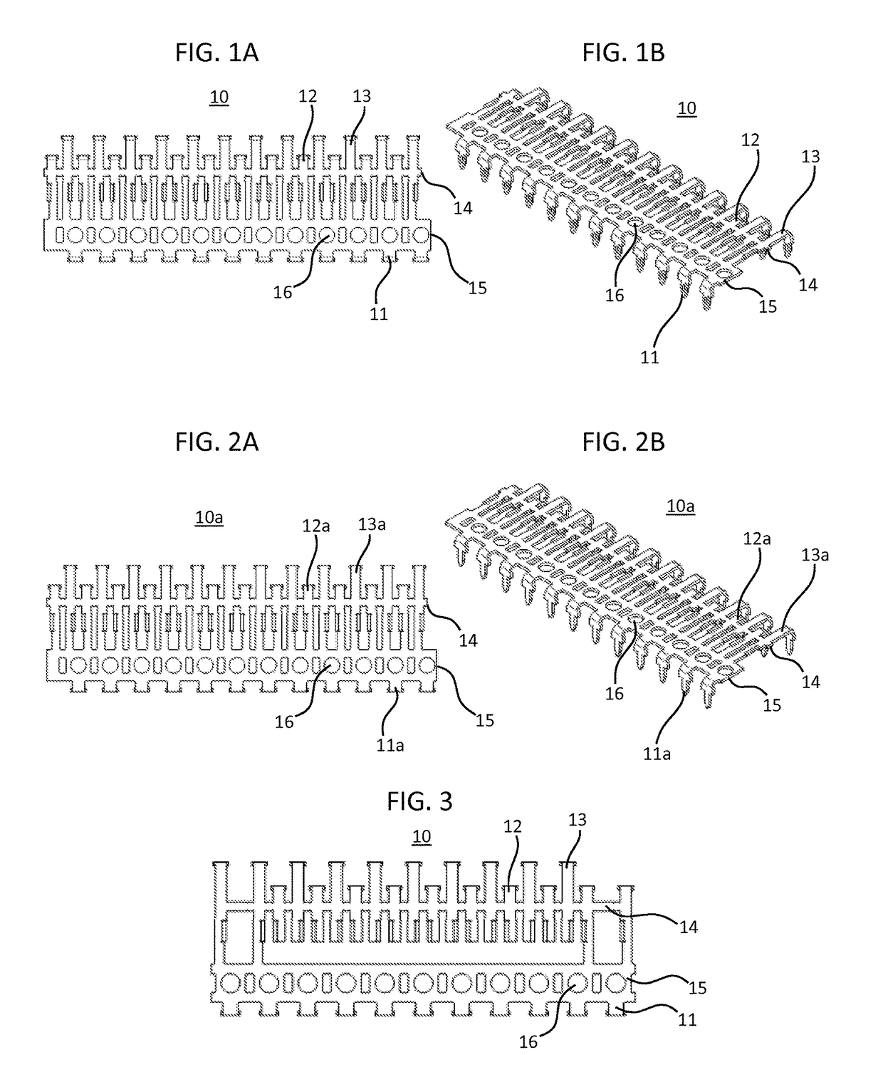
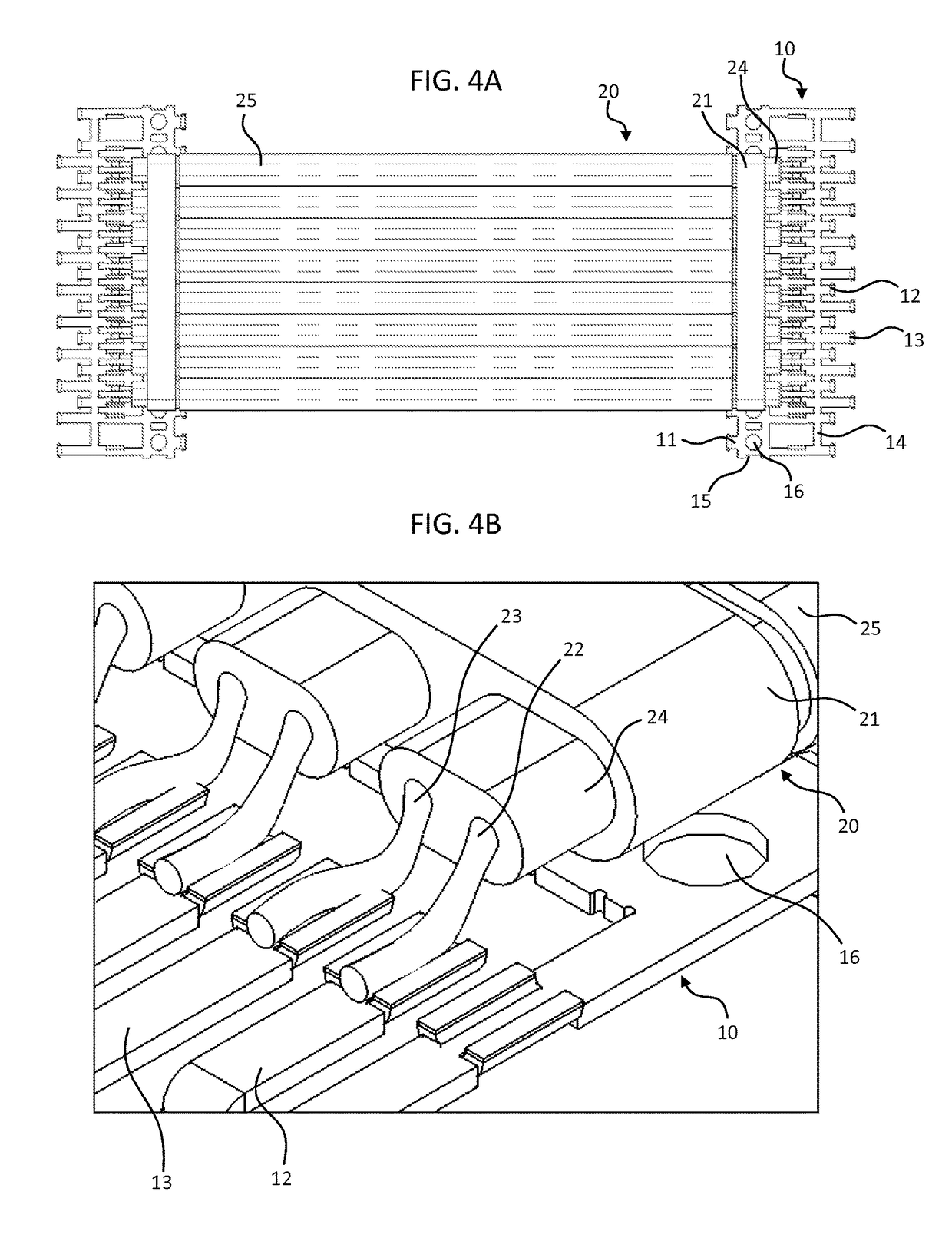
[0048]Preferred embodiments of the present invention will now be described in detail with reference to FIGS. 1 to 35. Note that the following description is in all aspects illustrative and not restrictive and should not be construed to restrict the applications or uses of the present invention in any manner.

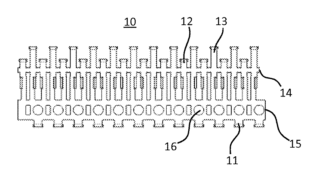
[0049]FIGS. 1A to 13B show a high-speed cable assembly according to a first preferred embodiment of the present invention. FIGS. 1A and 1B show a contact ribbon 10 in accordance with the first preferred embodiment of the present invention. The contact ribbon 10 includes one or more ground contacts 11, one or more first contacts 12, and one or more second contacts 13 to provide physical and electrical connections to, for example, a substrate or an electrical connector. The first contacts 12 and the second contacts 13 are preferably staggered or offset with respect to each other in respective rows to reduce the pitch of the high-speed cable assembly. Tie bars 14 connect the first a...


PUM

PropertyMeasurementUnit
transmission lengthaaaaaaaaaa
speedaaaaaaaaaa
frequencyaaaaaaaaaa

Abstract

A contact ribbon configured to connect a cable to a substrate includes a plurality of signal contacts, a ground plane, and at least one ground contact extending from the ground plane. The plurality of signal contacts are connected by a support member, and the support member is removable after the plurality of signal contacts are connected to the cable.

Description

BACKGROUND OF THE INVENTION[0001]1. Field of the Invention[0002]The present invention relates to connectors for high-speed signal transmission. More specifically, the present invention relates to connectors in which wires are directly connected to contacts of the connectors.[0003]2. Description of the Related Art[0004]High-speed cable routing has been used to transmit signals between substrates, such as printed circuit boards, of electronic devices. Conventional high-speed cable routing often requires routing in very tight and / or low-profile spaces. However, as data rates increase (i.e., the frequency of the high-speed signal increases), the cost of high-performance high-speed transmission systems increases as well. High-speed signals transmitted from between substrates generally follow a path of:[0005]1) a trace of the transmitting substrate;[0006]2) a first connector mounted to the transmitting substrate;[0007]3) a substrate of a second connector that is inserted into the first co...

Claims


Application Information

Patent Timeline
Patent Type & Authority Patents(United States)
IPC IPC(8): H01R12/00H01R43/16H01R12/59H01R9/03
CPCH01R43/16H01R12/592H01R9/032H01R12/594Y10T29/49174H01R13/65912
Inventor GUETIG, KEITH RICHARDVICICH, BRIAN RICHARDCOLLINGWOOD, ANDREW ROBERTELLIS, TRAVIS SCOTT
Owner SAMTEC
Why Eureka
Try Eureka