Composite valve with main valve element and sub-valve element

a valve element and composite technology, applied in the field of composite valves, can solve the problems of insufficient driving force, foreign materials entering the sliding portion of the valve, and eventually locking the main valve element, and achieve the effect of reducing the load of the actuating rod and being easy to transmi

Active Publication Date: 2017-08-15
TGK
View PDF11 Cites 23 Cited by
  • Summary
  • Abstract
  • Description
  • Claims
  • Application Information

AI Technical Summary

Benefits of technology

[0015]By employing this embodiment, the interlocking mechanism by the solenoidal force works even if the entry of foreign material into the guiding passage when the main valve is opened causes the main valve element to be locked. Displacing the actuating rod by the interlocking mechanism enables the sub-valve element to be displaced integrally with the actuating rod, so that the sub-valve can be reliably opened. Also, the pressing load, by which to press the main valve element in the closing direction of the main valve (i.e., in a direction that releases the locking), is increased by displacing the actuating rod relative to the main valve element after the sub-valve has been opened, so that the locking can be released. In this manner, the function of releasing the locked state of the main valve element and the function of opening / closing the sub-valve by the solenoidal force can both be achieved in a process of displacing the actuating rod.
[0017]By employing this embodiment, the pressing mechanism works according to magnitude of the solenoidal force even if the foreign material enters the spacing between the main valve element and the body when the main valve is opened. The pressing load, by which to press the main valve element in the closing direction of the main valve (i.e., in a direction that releases the locking), is increased by displacing the actuating rod relative to the main valve element by the pressing mechanism, so that the locking can be released. Also, the load of the actuating rod is reduced by releasing the clocked state of the main valve element, so that the solenoidal force is easily transmitted to the sub-valve element.

Problems solved by technology

Thus, it is problematic that there are many cases where foreign materials may enter its sliding portion and be entangled there.
In other words, the refrigerant discharged may contain the foreign material, such as metallic powders, which has come off as a result of friction of a piston in the compressor, and the foreign material may enter the sliding portion between the main valve element and the body to prevent a smooth movement of the main valve element and may eventually lock the main valve element at the worst case.
In such a case, as cited in Reference (1), for example, there are cases where the structure, in which the main valve element is biased by the spring alone, cannot provide a driving force sufficient to operate the main valve element in a valve closing direction, even though the compressor is turned on again.
In this case, it is difficult to start the compressor even though the sub-valve can be opened.
However, this structure does not allow the actuating rod to displace the sub-valve element relative to the main valve element, so that the sub-valve cannot be opened according to the solenoidal force.
This creates an undesirable conflict.
Note that such problems may occur not only in the control valve for a variable displacement compressor as cited in Reference (1) but also in a composite valve where the main valve and the sub-valve are driven by a single solenoid.

Method used


Image

  • Composite valve with main valve element and sub-valve element
  • Composite valve with main valve element and sub-valve element
  • Composite valve with main valve element and sub-valve element

Examples


first embodiment

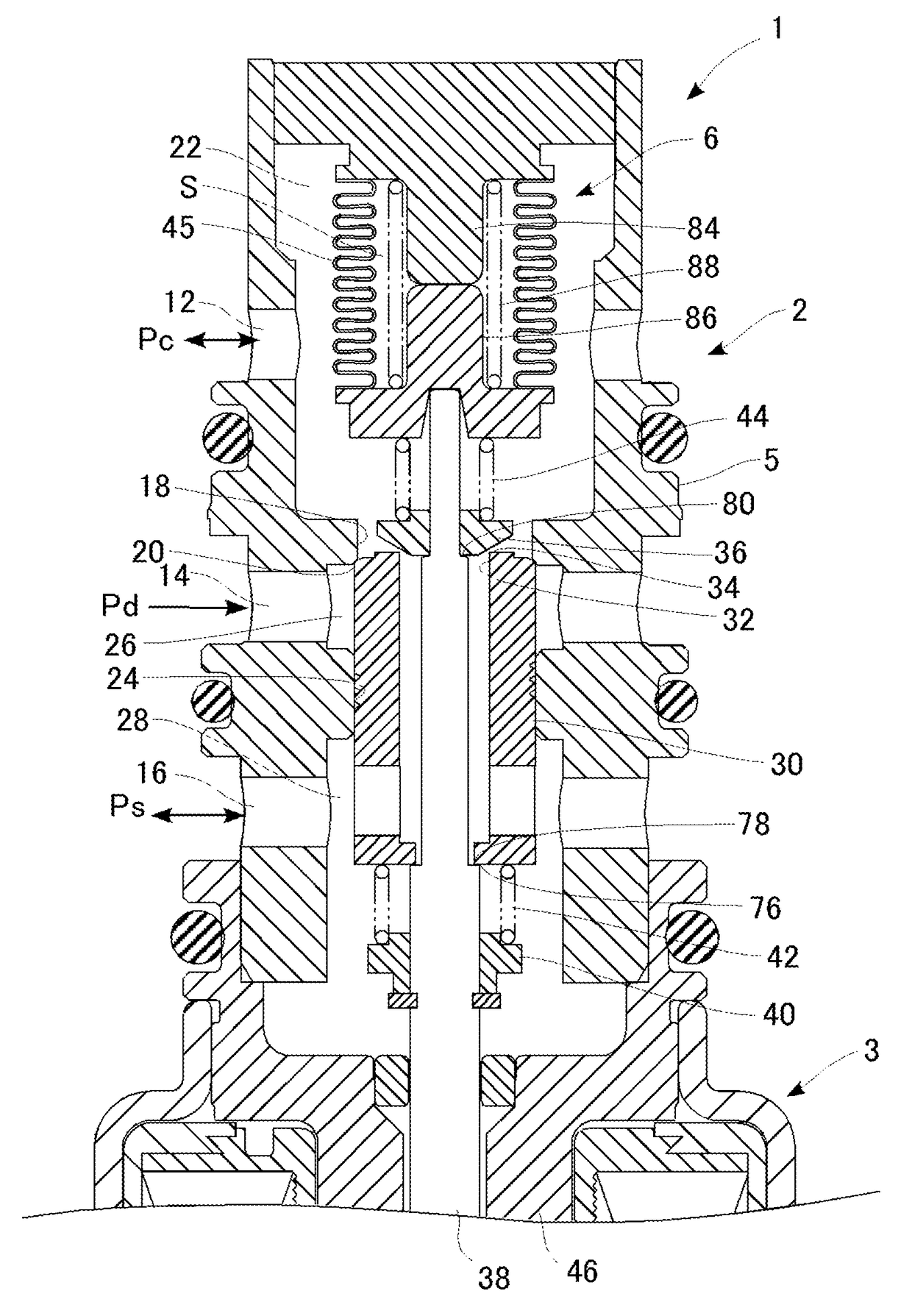
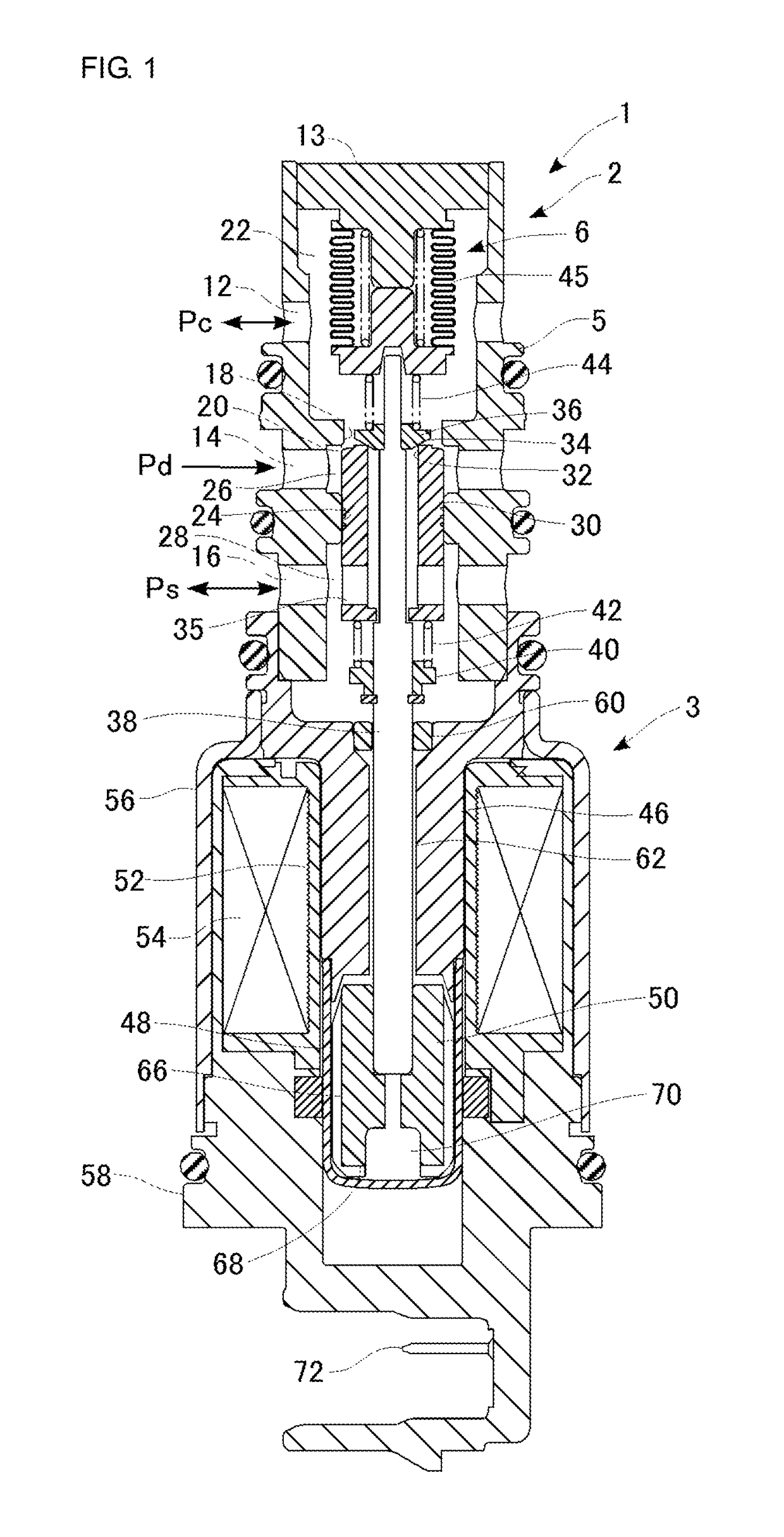
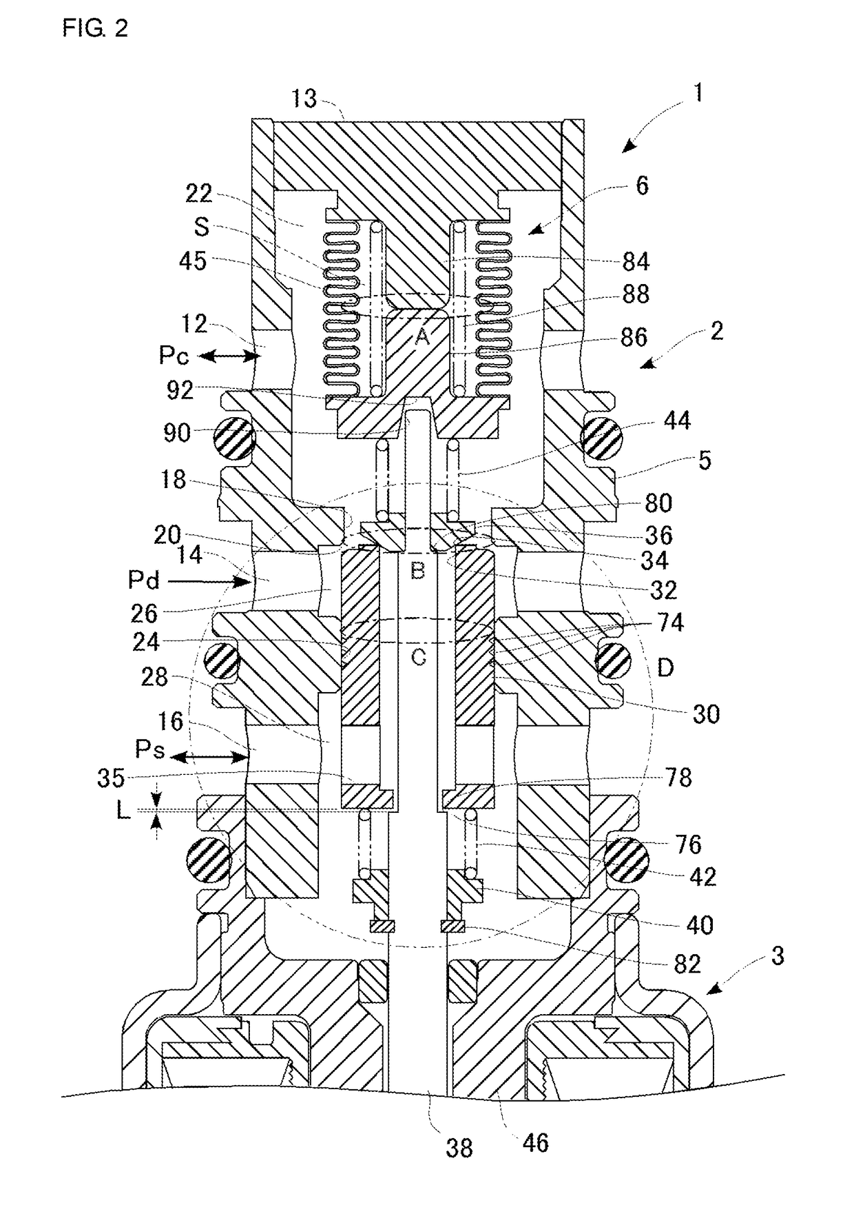
[0031]FIG. 1 is a cross-sectional view showing a structure of a control valve according to a first embodiment. A control valve 1 is configured as an electromagnetic valve for controlling a discharging capacity of a not-shown variable displacement compressor (hereinafter referred to simply as “compressor”) installed for a refrigeration cycle of an automotive air conditioner. This compressor discharges a high-temperature and high-pressure gaseous refrigerant produced by compressing a refrigerant flowing through the refrigeration cycle. The gaseous refrigerant is then condensed by a condenser (external heat exchanger) and further adiabatically expanded by an expander so as to become a misty, low-temperature and low-pressure refrigerant. This low-temperature and low-pressure refrigerant is evaporated by an evaporator, and the evaporative latent heat cools the air of an interior of a vehicle. The refrigerant evaporated by the evaporator is again brought back to the compressor and thus ci...

second embodiment

[0069]FIG. 8 is a cross-sectional view showing a structure of a control valve according to second embodiment. FIG. 9 is a partially enlarged sectional view of the upper half of FIG. 8. The control valve according to the second embodiment differs from the first embodiment in the structure of the valve unit. Thus, a description is hereinbelow given centering around different features therefrom. Note that the structural components in FIG. 8 and FIG. 9 closely similar to those of the first embodiment are given the identical reference numerals.

[0070]As shown in FIG. 8, a control valve 201 is constituted as a Ps sensing valve. However, a power element 206 does not sense the crank pressure Pc but directly senses the suction pressure Ps, instead. The control valve 201 according to the second embodiment differs from the first embodiment in this respect. The control valve 201 is constituted by integrally assembling a valve unit 202 and a solenoid 203. In the present embodiment, too, a body 20...

third embodiment

[0078]FIG. 10 is a partially enlarged sectional view of the upper half of a control valve according to a third embodiment. The control valve according to the third embodiment differs from the first and second embodiments in the structure of the valve unit. Thus, a description is hereinbelow given centering around different features therefrom. Note that the structural components in FIG. 10 closely similar to those of the first and second embodiments are given the identical reference numerals.

[0079]A control valve 301 shares the same feature, where a power element 306 directly senses the suction pressure Ps, as the second embodiment and differs from the first and second embodiments in that the sub-valve seat 34 is provided in a housing 307 instead of in a main valve element 330. The control valve 301 is constituted by integrally assembling a valve unit 302 and a solenoid 303. In the present embodiment, too, a body 305, a housing 307, a core 346, a casing 56 and an end member 58 form a...


PUM


Abstract

A control valve according to an exemplary embodiment includes an interlocking mechanism that achieves a first operation and a second operation simultaneously or continuously. In the first operation, a sub-valve is opened by having an actuating rod displaced integrally with a sub-valve element in accordance with the magnitude of solenoidal force. In the second operation, a load, by which to bias a main valve element in a closing direction of a main valve, is increased by displacing the actuating rod relative to the main valve element.

Description

CLAIM OF PRIORITY TO RELATED APPLICATION[0001]The present application is claiming priority of Japanese Patent Application No. 2012-250958, filed on Nov. 15, 2012, the content of which is incorporated herein by reference.BACKGROUND OF THE INVENTION[0002]1. Field of the Invention[0003]The present invention relates to a composite valve and it particularly relates to a composite valve, provided with a main valve and a sub-valve in a common body, which is driven by a single solenoid.[0004]2. Description of the Related Art[0005]An automotive air conditioner generally includes a compressor, a condenser, an expander, an evaporator, and so forth. Here, the compressor discharges a high-temperature and high-pressure gaseous refrigerant produced by compressing a refrigerant flowing through a refrigeration cycle of a vehicle. The condenser condenses the gaseous refrigerant. The expander produces a low-temperature and low-pressure refrigerant by adiabatically expanding the condensed liquid refrig...

Claims


Application Information

Patent Timeline
Patent Type & Authority Patents(United States)
IPC IPC(8): F16K31/06F04B27/18
CPCF16K31/0603F04B27/1804F16K31/0613F04B2027/1813F04B2027/1827F04B2027/1831Y10T137/86879F16K31/06
Inventor SAEKI, SHINJIKANEKO, YUUKITONEGAWA, MASAAKI
Owner TGK
Why Eureka
Try Eureka