Low-impact overall ejection type launching canister front cover

A catapult launch, low-impact technology, applied in launch devices, rocket launch devices, offensive equipment, etc., can solve the problems of safety impact, limited flight distance, complex structure, etc., to reduce the impact force of the projectile, and respond quickly. , the effect of reliable opening

Inactive Publication Date: 2015-11-11
BEIJING INSTITUTE OF TECHNOLOGYGY
View PDF7 Cites 13 Cited by
  • Summary
  • Abstract
  • Description
  • Claims
  • Application Information

AI Technical Summary

Problems solved by technology

Among them, the electromechanical front cover uses a motor to drive a special mechanism to realize the opening of the cover before launch. Its structure is more complicated and the launch preparation time is longer; the integral detachment front cover uses gas shock waves, projectile impact force or explosive cables as power. In the initial stage of ignition of the booster engine, the overall falling off of the cover usually requires a relatively large impact force or explosive force, which has high requirements on the impact resistance of the projectile, and the flight distance when the cover falls off is limited, which is harmful to the projectile and the launch. The safety of the device has a certain impact; the fragile front cover also uses the gas shock wave or projectile impact force as the power to realize the opening and falling of the cover, and breaks into multiple pieces to reduce the impact on launch safety. The cover needs to prefabricate the broken groove and ensure its strength during storage and transportation, which is difficult to realize in the process

Method used


Image

  • Low-impact overall ejection type launching canister front cover
  • Low-impact overall ejection type launching canister front cover
  • Low-impact overall ejection type launching canister front cover

Examples


Embodiment Construction

[0030] The present invention will be described in detail below with reference to the drawings and embodiments.

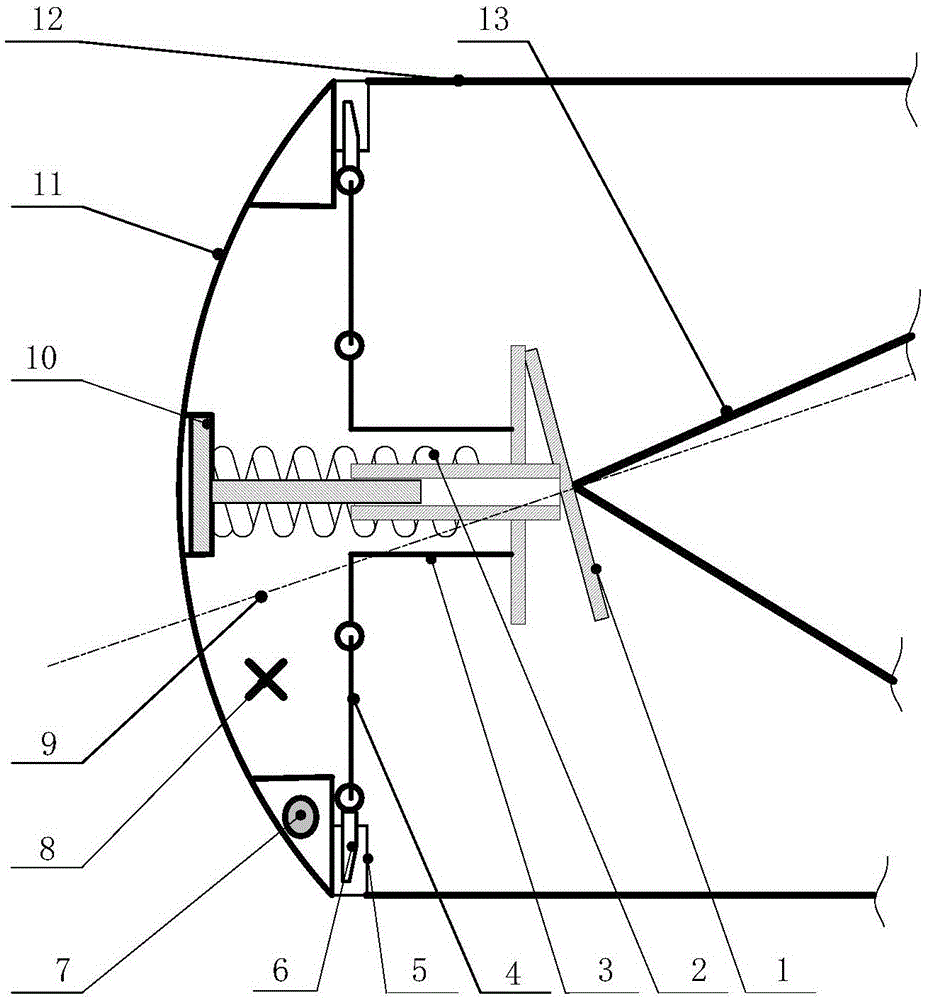
[0031] The invention provides a front cover of a low-impact integral ejection type launching box, see attached figure 1 , Including: energy storage ejection mechanism, locking / unlocking mechanism and front cover body structure;

[0032] Its peripheral equipment includes: launching box 12 and projectile 13;

[0033] The energy storage ejection mechanism includes: a movable impact component 1, an energy storage spring 2 and a fixed strut 3;

[0034] The locking / unlocking mechanism includes: pull rod 4, fixed locking ring 5 and locking tongue 6;

[0035] The front cover body structure includes: a front cover body 11, a fixed support 10 and a counterweight 7;

[0036] The movable impact component 1 is composed of a flat plate, an inclined plate and a hollow tube. The flat plate and the inclined plate are fixedly connected at an acute angle, and the hollow tube is vertically fixed ...


PUM


Abstract

The invention discloses a low-impact overall ejection type launching canister front cover and belongs to the technical field of rocket and missile launching. The low-impact overall ejection type launching canister front cover comprises a movable impact part, an energy storage spring, fixing fulcrum bars, pull bars, fixing locking rings, locking tongue pieces, a front cover body and a fixed support. The fixed support is fixed to the center of the front cover body. A hollow pipe of the movable impact part and a guide bar of the fixed support are in hole and shaft fit. The outer surface of the hollow pipe of the movable impact part and the outer surface of the guide bar of the fixed support are sleeved with the energy storage spring. One end of each fixing fulcrum bar is fixed to a flat plate of the movable impact part. One end of each pull bar is movably connected to the other end of the corresponding fixing fulcrum bar. Each locking tongue piece is movably connected to the other end of the corresponding pull bar. The fixing locking rings are fixed to flanges of a launching canister body. The front cover body is installed at the open end of the launching canister body through the cooperation of the locking tongue pieces and the fixing locking rings. The launching canister front cover can be effectively sealed and reliably opened and safely disengage.

Description

Technical field [0001] The invention belongs to the technical field of rocket and missile launching, and specifically relates to a front cover of a low-impact integral ejection type launching box. Background technique [0002] The front cover of the rocket and missile launching box is an important part of the rocket and missile launching box. During the storage and transportation process, the front cover guarantees the effective sealing of the launch box, providing a suitable storage and transportation environment for rockets and missiles; during the launch process, the front cover needs to be reliably opened and safely detached to ensure the safe launch of the projectile. The design of the front cover of the launch box has always been an important part of the design of rockets and missile launchers. The key points include: 1) Reduce the time of opening the front cover and improve the launch efficiency; 2) Reduce the impact of the opening of the front cover on the projectile body...

Claims


Application Information

Patent Timeline
Patent Type & Authority Applications(China)
IPC IPC(8): F41F3/042F41F7/00
Inventor 傅德彬王新星
Owner BEIJING INSTITUTE OF TECHNOLOGYGY
Why Eureka
Try Eureka