Tool for grouting in loose coal seam section during drilling

A loose-while-drilling technology, used in earth-moving drilling, wellbore/well components, sealing/packaging, etc., can solve problems such as abnormality and low normal rate of hole formation, and achieve correct opening, convenient operation and safety. Good results

Inactive Publication Date: 2012-02-01
CHINA UNIV OF GEOSCIENCES (WUHAN)
View PDF4 Cites 13 Cited by
  • Summary
  • Abstract
  • Description
  • Claims
  • Application Information

AI Technical Summary

Problems solved by technology

However, the normal rate of hole formation is generally low, which can be described as "nine out of ten drills are abnormal".

Method used


Image

  • Tool for grouting in loose coal seam section during drilling
  • Tool for grouting in loose coal seam section during drilling
  • Tool for grouting in loose coal seam section during drilling

Examples


Embodiment 1

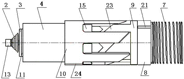
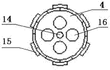
[0033] Embodiment 1: a kind of coal seam loose section while drilling grouting tool of the present invention, its structure is as follows figure 1 , 2 , 3 shown. It includes a one-way valve, valve seat 4, ratchet control mechanism, housing and nozzle 5. The one-way valve is composed of a pallet shaft 1, a valve spring 2, a pallet 3, a rubber pad 11, and a valve nut 13. The valve Seat 4 is a cylinder, one end of the cylinder has a straight groove with beveled sides for guiding and limiting, the other end has a round end face, and the center of the round end face has a pallet shaft hole 14, and the pallet shaft 1 is installed on the pallet shaft In the hole 14, the valve spring 2, the tray 3, and the rubber pad 11 are limited on the tray shaft 1 by the valve nut 13;

[0034] Ratchet control mechanism among the present invention, see figure 2 , 3 , consisting of a ratchet spring 7, a sliding plate 8, a turntable 9, and a fixed groove 10, the end face of the slide plate 8 is ...

Embodiment 2

[0041] Embodiment 2: A grouting tool for drilling loose sections of coal seams according to the present invention is used for drilling loose sections of underground coalbed methane extraction and other underbalanced drilling projects. When in use, it is transmitted through reverse circulation: "normal drilling" and "grouting drilling" commands, the control signal transmission method is the same, the circulating medium is atomized wind, the pressure is 0.5-0.7MPa, "normal drilling" fog The wind flow is positive, such as Figure 12 shown.

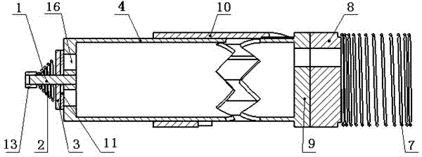
[0042] When the signal of "normal drilling" or "grouting drilling" is transmitted, the atomization air flow is reversed, that is, it flows in from the annular gap between the drill pipe and the drill hole, enters the drill pipe through the drill bit, and is driven by the pallet shaft 1, valve spring 2, The one-way valve composed of tray 3, rubber pad 11 and valve nut 13 is closed. Under the action of wind force, the valve seat 4 moves to the...


PUM


Abstract

The invention relates to a tool for grouting in a loose coal seam section during drilling, which comprises a one-way valve, a valve seat, a ratchet wheel control mechanism, a shell and a nozzle. A tray shaft is arranged in a tray shaft hole, a valve spring, a tray and a rubber pad are limited on the tray shaft through a valve nut; the ratchet wheel control mechanism comprises a ratchet wheel spring, a sliding plate, a rotating plate and a fixed slot, the two sides of the sliding plate are provided with the ratchet wheel spring and the rotating plate, and the end faces of the sliding plate and the rotating plate have the same diameter and are provided with three through holes with the same design; when control signals are not executed, the fixed slot is sleeved outside the valve seat and the rotating plate, and a fixed slot bulge is arranged on the fixed slot and is clamped in a short slot in a sleeve for positioning in the sleeve; and the shell comprises a short drill bit joint and the sleeve, and the nozzle is arranged on the outer wall of the sleeve. The two ends of the shell are connected with a drill bit and a drill stem through pipe threads and are provided with a sealing ring. The grouting tool has a simple structure, normal drilling and grouting type drilling can be achieved via mechanical signal transmission and control, and the tool can be used safely and reliably and is suitable for drilling of loose sections after gas exploration in underground coal seams and also other under-balanced drilling projects.

Description

technical field [0001] The invention relates to a drilling-while-drilling grouting tool for loose sections of coal seams. Background technique [0002] The contradiction between mining connection and extraction connection, and the contradiction between drainage and production land grabbing are the main contradictions in underground drainage methods. Coupled with the need for intensive drilling, construction personnel are required to drill holes "efficiently". "High efficiency" is reflected in two aspects, namely short drilling cycle and high normal rate of hole formation. At present, underbalanced drilling is used in the drilling of underground gas extraction holes, mainly using air / atomization drilling, and the drilling cycle is greatly shortened. Some foreign scholars believe that the cycle of underbalanced drilling is 1 / 10 of the cycle of ordinary mud drilling, which meets the needs of the project. . However, the normal rate of hole formation is generally low, which ca...

Claims


Application Information

Patent Timeline
Patent Type & Authority Applications(China)
IPC IPC(8): E21B33/13
Inventor 路桂英王院生张永权乌效鸣王生维
Owner CHINA UNIV OF GEOSCIENCES (WUHAN)
Why Eureka
Try Eureka