Fuel tank

a technology for fuel tanks and fuel injection tanks, which is applied in the direction of liquid fuel feeders, machines/engines, bends, etc., can solve the problems of high manufacturing cost of fuel tanks, low productivity and endurance reliability, and large number of components in the above fuel tank b>1/b>, so as to achieve reliable and reliable opening.

Active Publication Date: 2012-05-17
HONDA MOTOR CO LTD
View PDF9 Cites 14 Cited by
  • Summary
  • Abstract
  • Description
  • Claims
  • Application Information

AI Technical Summary

Benefits of technology

[0010]The present invention has been made in an effort to solve the above problems. An object of the present invention is to provide a fuel tank having a simple and economical structure, which is capable of obtaining a desired siphon effect and using the fuel in the fuel tank efficiently.
[0013]According to the present invention, when a gaseous layer (gaseous atmosphere) exists in the tank interior and a liquid layer (liquid atmosphere) is produced in the siphon tube, the lid is displaced by the liquid pressure from the siphon tube thereby to open the opening. Owing thereto, without any influence being imparted due to the size (and weight) of the float member, the opening can reliably be opened in a gaseous atmosphere, and fuel can suitably be introduced into the tank interior from the siphon tube.
[0014]In addition, the float member floats on the fuel and then causes the lid to be displaced due to the liquid level of the fuel rising within the tank, thereby enabling the opening to be opened. Consequently, even if an abrupt rise of the liquid level of the fuel occurs as a result of supplying fuel or the like, due to the buoyancy of the float member, the lid is displaced and the opening can reliably be opened. Thus, introduction of fuel into the siphon tube from the interior of the tank can smoothly be carried out.

Problems solved by technology

However, the above fuel tank 1 is made up of a large number of components and is complex in structure, because the fuel tank 1 includes actuating parts such as the filter having small openings therein, the diaphragm, and the like, as well as the flow valve assembly.
For this reason, problems result in that the fuel tank is costly to manufacture and is low in productivity and endurance reliability.
Furthermore, the fuel undergoes a large pressure loss due to the fact that the fuel flows through the filter having small openings therein, thereby resulting in a reduced siphon transfer speed.
Accordingly, the filter tends to become clogged with dirt and may also suffer from damage.
Additionally, since the filter of the aforementioned fuel tank 1 has a liquid filter structure, the filter fails to provide a sealing function when the filter is dry or is not in a wetted state.
Therefore, the filter cannot prevent air from flowing therethrough, and a problem results in that the filter does not provide a stable siphoning effect.

Method used


Image

  • Fuel tank
  • Fuel tank
  • Fuel tank

Examples


first embodiment

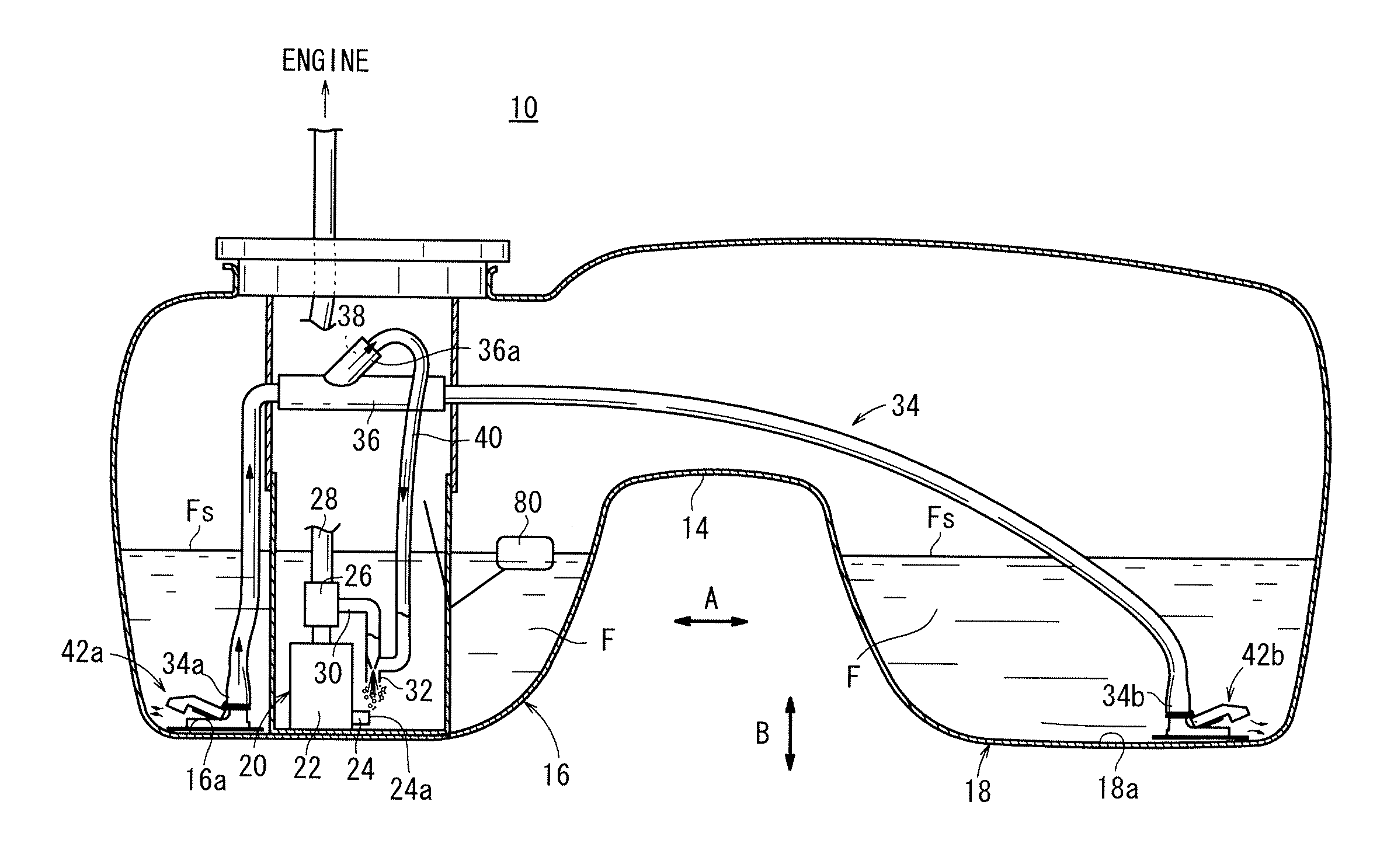
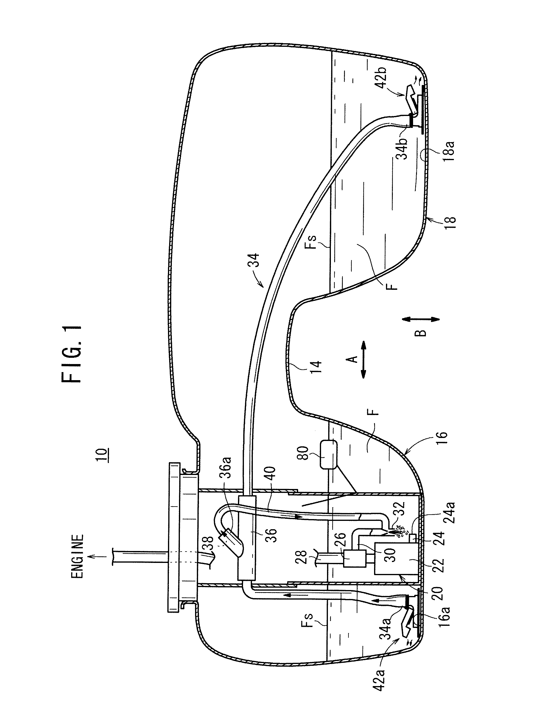
[0026]As shown in FIG. 1, a fuel tank 10 according to the present invention comprises a saddle type fuel tank, which is mounted on a vehicle, not shown. The fuel tank 10 includes an upwardly curved saddle 14 on a bottom substantially central portion thereof in the width direction (indicated by the arrow A) of the vehicle. The saddle 14 forms a main tank (first reservoir) 16 and a sub-tank (second reservoir) 18 in the fuel tank 10.

[0027]A fuel pump module 20 is disposed in the main tank 16. The fuel pump module 20 comprises a fuel pump 22, including a pumping jet pump 24 that has a fuel intake port 24a, which opens toward the bottom of an inner surface 16a of the main tank 16, and also including a pressure regulator 26 connected to an outlet side of the fuel pump 22.

[0028]The pressure regulator 26 supplies fuel F to a non-illustrated engine through a fuel pipe 28, and has a suction branch pipe 30 extending therefrom. The branch pipe 30 has a distal end (lower end) connected to a suct...

second embodiment

[0055]FIG. 7 is an outline perspective view of fuel introducing members 90a, 90b that make up part of a fuel tank according to the present invention.

[0056]Constituent elements of the second embodiment, which are the same as those of the fuel tank 10 according to the first embodiment, are denoted by identical reference characters and detailed explanations of such features are omitted. Similar constituent elements of the third embodiment, also to be described below, are treated in the same manner and detailed explanations thereof shall be omitted.

[0057]As shown in FIGS. 7 and 8, the lid 92 of each of the fuel introducing members 90a, 90b has an insert 94 which is formed to bulge upwardly in a disk-shaped central region thereof, with an auxiliary float member 96 being mounted on the insert 94. The auxiliary float member 96 is formed to be lighter in weight than the float member 70, and in a gaseous atmosphere, the auxiliary float member 96 together with the lid 92 is swingable by liqui...

third embodiment

[0060]FIG. 9 is an outline perspective view of fuel introducing members 110a, 110b that make up part of a fuel tank according to the present invention.

[0061]As shown in FIGS. 9 and 10, a float member 112, which makes up part of each of the fuel introducing members 110a, 110b, has a dimension that is large in the height direction, and is formed with a concavity 114 in an interior portion thereof. The concavity 114 is set to a dimension that is capable of accommodating swingability of the lid 92 within a predetermined angular range.

[0062]The third embodiment, which is constructed in the foregoing manner, can obtain the same advantages and effects as those of the above first and second embodiments.


PUM


Abstract

A fuel introduction member is connected to an open end of a siphon tube which constitutes a part of a fuel tank. The fuel introduction member is provided with an opening through which a fuel is introduced from the tank into the siphon tube and from the siphon into the tank, a lid portion which is swung by the hydraulic pressure from the siphon tube so as to open the opening, and a float member which floats on the fuel in accordance with the rise of a fuel liquid surface in the tank to displace the lid portion in order to open the opening.

Description

TECHNICAL FIELD[0001]The present invention relates to a fuel tank including a first reservoir and a second reservoir for reserving fuel, a siphon tube that extends between the first reservoir and the second reservoir, and which transfers the fuel by a negative pressure generator, and a fuel introducing member connected to at least one open end of the siphon tube.BACKGROUND ART[0002]Fuel tanks are used to supply fuel to internal combustion engines. For example, 4WD (four-wheel-drive) vehicles and FR (front engine, rear wheel drive) vehicles use a so-called saddle type fuel tank, the bottom of which is upwardly recessed at a center portion in the width direction of the vehicle in order for the fuel tank to avoid physical interference with a propeller shaft, which extends down the middle of the vehicle.[0003]A saddle fuel tank generally is divided into a first reservoir for reserving fuel and a second reservoir for reserving fuel. Each of the first reservoir and the second reservoir is...

Claims


Application Information

Patent Timeline
Patent Type & Authority Applications(United States)
IPC IPC(8): F04F10/00
CPCB60K15/077B60K2015/03111B60K2015/03118B60K2015/03138B60K2015/03217F02M37/106F02M37/0023F02M37/0058F02M37/0094F02M37/025F02M37/103B60K2015/0325Y10T137/2849Y10T137/7485Y10T137/4841Y10T137/86075Y10T137/2713
Inventor MURABAYASHI, SHINYAKOBAYASHI, KENGO
Owner HONDA MOTOR CO LTD
Why Eureka
Try Eureka