Ultrasonic flow meter with digitally under-sampled flow measurements

a flow meter and ultrasonic technology, applied in the field of ultrasonic flow meter, can solve the problems of high-speed adcs, high cost, and dramatic change of signal shape, and achieve the effects of low cost, low cost, and low cost of flow meter

Active Publication Date: 2017-08-15
KAMSTRUP
View PDF26 Cites 2 Cited by
  • Summary
  • Abstract
  • Description
  • Claims
  • Application Information

AI Technical Summary

Benefits of technology

[0008]It would be advantageous to achieve alternative methods of operating an ultrasonic flow meter which achieves at least one of: facilitates a cost-efficient flow meter, can be operated in an energy efficient manner to sustain long-life battery power, and which supports operation for many years with no or only little development in the accuracy of the time measurements. It would also be advantageous to achieve a method of operating an ultrasonic flow meter which is robust to variations of the electro-mechanical characteristic of the utilized components. In general, the invention preferably seeks to mitigate, alleviate or eliminate one or more disadvantages of flow meters of the prior art, singly or in any combination.
[0018]The inventors of the present invention have realized that by proper signal treatment of the received signal, it is feasible to determine the difference in propagation time in a situation with an under-sampled received signal with a sufficient accuracy, even without reconstructing the received signal. By under-sampling the received signal, the performance demands of the ADC can be loosened, leading to a cheaper component which requires less power, than an ADC used in the prior art. By not reconstructing the received signal, but determining the difference in propagation time based on signal treatment of the digitized received under-sampled signals, fewer samples and thereby fewer instructions are needed to be dealt with by the digital signal processor, and thereby reducing the performance demands also of the micro-processor that performs the digital signal processing.

Problems solved by technology

Signal transformation from the transmitter to the receiver can make it challenging to extract the parameters which are important to the flow rate calculation.
In particular, the electro-mechanical parameters of the piezo-electrical transducers normally lead to a dramatically change of the signal shape.
High-speed ADCs are however expensive and consume a relative high amount of power, and therefore jeopardize the battery life time of battery powered meters, and becomes an important component for the price level of the meter.

Method used


Image

  • Ultrasonic flow meter with digitally under-sampled flow measurements
  • Ultrasonic flow meter with digitally under-sampled flow measurements
  • Ultrasonic flow meter with digitally under-sampled flow measurements

Examples


Embodiment Construction

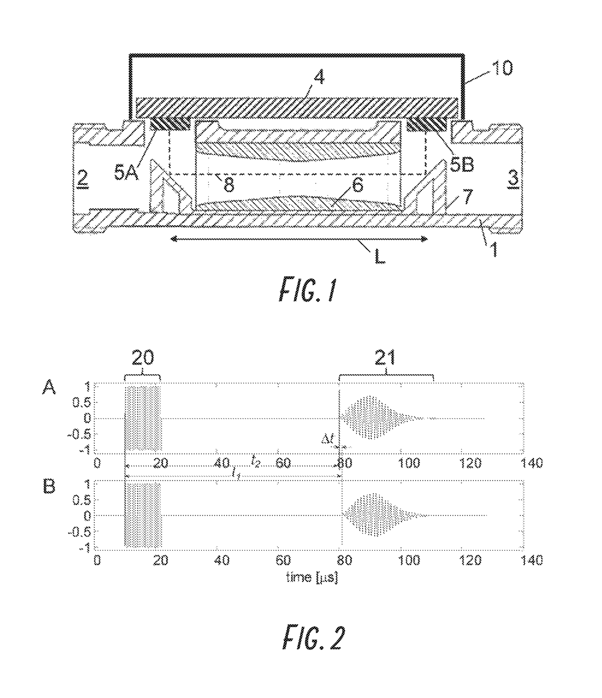
[0033]FIG. 1 illustrates a schematic cross-sectional view of elements of an embodiment of an ultrasonic flow meter. The flow meter comprises a housing 1, or flow tube, with an inlet 2 and outlet 3. The flow meter further comprises an electronic unit 4 comprising or connected to ultrasonic transducers 5A, 5B. The flow meter comprises a measuring distance L, defined by a measuring insert 6. In general, however, the measuring distance need not be defined by an insert, but could be an integral part of the housing 1, such as a through-going flow channel of the housing. The ultrasonic transducers 5A, 5B for generating and detecting ultrasonic signals are placed so that the generated signals can be introduced into the measuring distance. In the illustrated embodiment, reflectors 7 are placed so that the signals 8 emitted from each of the transducers are directed along the measuring distance, and onto the opposite transducer for detection.

[0034]Signals propagating downstream propagate faste...


PUM


Abstract

The invention relates to a method of operating an ultrasonic flow meter by digitally sampling received signals. Acoustic wave packets are transmitted through a measuring distance in opposite directions, and the received signals are digitized at a sampling frequency being below the Nyquist-limit of two times the signal frequency of the wave packet to generate digitized under-sampled signals 31. From the digitized under-sampled signals, the difference in propagation time along the measuring distance is determined.

Description

CROSS REFERENCE TO RELATED APPLICATIONS[0001]This application is a U.S. National Phase Application of PCT International Application Number PCT / DK2012 / 050440, filed on Nov. 30, 2012, designating the United States of America and published in the English language, which is an International Application of and claims the benefit of priority to European Patent Application No. 11191677.1, filed on Dec. 2, 2011. The disclosures of the above-referenced applications are hereby expressly incorporated by reference in their entireties.FIELD OF THE INVENTION[0002]The invention relates to an ultrasonic flow meter, and in particular to a method of operating the ultrasonic flow meter by digitally sampling received signals.BACKGROUND OF THE INVENTION[0003]In a consumption ultrasonic flow meter of the transit time type, the determination of the consumption is based on a flow rate measurement of the consumed medium. The flow rate measurement is based on measuring a transit time difference between count...

Claims


Application Information

Patent Timeline
Patent Type & Authority Patents(United States)
IPC IPC(8): G01F1/66G06F17/40G06F19/00G01P5/24
CPCG01F1/66G01F1/662G01F1/667G01P5/245G06F17/40G06F19/00G16Z99/00
Inventor SORENSEN, JENS LYKKEBENDIXEN, PAUL MARTIN
Owner KAMSTRUP
Why Eureka
Try Eureka