Ultrasonic flow meter with zero impedance measuring electronics

a technology of electronics and ultrasonic flow meter, which is applied in the direction of volume/mass flow measurement, measurement devices, instruments, etc., can solve the problems of time-consuming and expensive operation, affecting the fabrication of small flow meters, and transforming into measurement uncertainty. , to achieve the effect of short, highly precise ultrasonic flow meters

Inactive Publication Date: 2013-08-15
KAMSTRUP
View PDF6 Cites 9 Cited by
  • Summary
  • Abstract
  • Description
  • Claims
  • Application Information

AI Technical Summary

Benefits of technology

[0008]It would be advantageous to achieve an ultrasonic flow meter which is not restricted by a minimal travel time of the ultrasonic signal, which is nevertheless capable of measuring the travel time with a high precision without individual adjustment of the electronic circuit. Moreover, it would be advantageous to achieve an ultrasonic flow meter which is less sensitive to the electro-mechanical characteristics of the transducers. In general, the invention preferably seeks to mitigate, alleviate or eliminate one or more disadvantages of flow meters of the prior art, singly or in any combination.
[0018]The separate electronic circuits for generating and receiving electrical signals to and from the ultrasonic transducers together with the switch configuration which are set prior to a flow measurement, and the restriction of the output impedance and input impedance to substantially zero thus provides a synergic effect which enables the provision of short highly precise ultrasonic flow meters. Nevertheless, the invention may also advantageously be used in connection with other types of flow meters, since the aspect of render the flow determination less sensitive to the transducer characteristics, and since any restrictions arising from a need to shift the switches while the signal is traversing the medium are removed, are aspects which may also be beneficial in other types of flow meters as well.
[0019]In important embodiments, the generator circuit and the receiver circuit are based on operational amplifiers with the non-inverted input connected to a reference source and the inverted input connected to the transducers via the transducer switching means. In such a configuration, the operational amplifiers fix the impedance by which the transducers are loaded, to virtually zero ohms. A setup of this type therefore ensures that the ultrasonic transducers always see the same impedance, i.e. zero or almost zero, irrespective of whether they operate as transmitters or as receivers. An advantage of these embodiments is that impedance matching of individual circuits is not needed during manufacturing to compensate for impedance variations between, in principle identical, electronic components, since such a compensation is not need, as the electrical properties of a properly configured operation amplifier ensures that the inverted input is kept at an impedance of zero ohms.

Problems solved by technology

Any difference in the impedances in these two situations will translate into a measurement uncertainty.
Consequently a certain distance must be covered by the ultrasonic wave inside the flow meter, hindering among other things, the fabrication of small flow meters.
This is a time consuming and expensive operation to perform on each flow meter circuit.

Method used


Image

  • Ultrasonic flow meter with zero impedance measuring electronics
  • Ultrasonic flow meter with zero impedance measuring electronics
  • Ultrasonic flow meter with zero impedance measuring electronics

Examples


Embodiment Construction

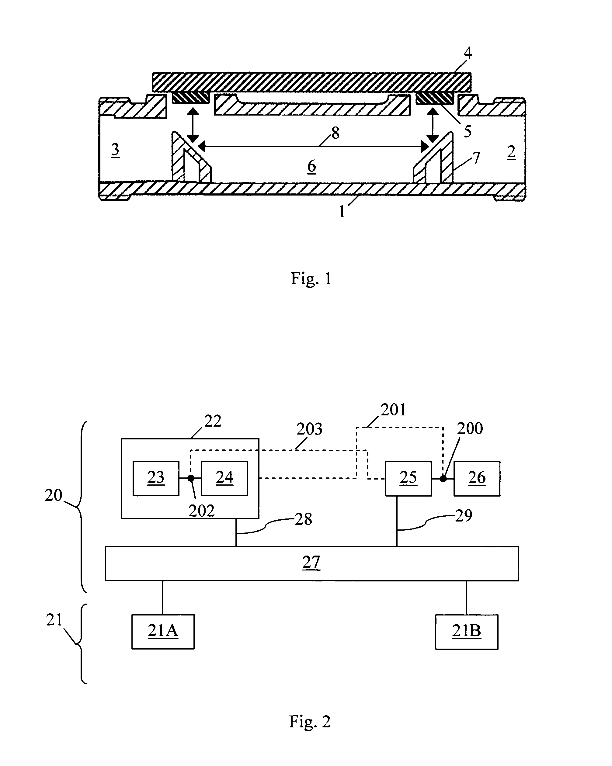
[0037]FIG. 1 illustrates a schematic cross-sectional view of an embodiment of an ultrasonic flow meter in the form of a consumption meter. The flow meter comprises a housing 1 with an inlet 2 and outlet 3. The flow meter further comprises an electronic unit 4 comprising or connected to ultrasonic transducers 5. The flow meter comprises a measuring distance 6, here schematically illustrated by a through going channel. The ultrasonic transducers 5 for generating and detecting ultrasonic signals are placed so that the generated signals can be introduced into the measuring distance. Reflectors 7 are placed so that the signals 8 emitted from each of the transducers are directed along the flow passage, and onto the opposite transducer for detection. Signals propagating upstream propagate faster than signals propagating downstream, and the flow rate can be determined by measuring difference in arrival time of the emitted signals at the other transducers. The determination of the flow rate,...


PUM


Abstract

The present invention discloses an ultrasonic flow meter comprising a generator circuit and a receiver circuit electrically separated from the generator circuit. The flow meter further comprises transducer switching means for controlled connection of ultrasonic transducers to either the generator circuit or to the receiver circuit. The output impedance of the generator circuit and the input impedance of the receiver circuit are controlled to be substantially zero.

Description

FIELD OF THE INVENTION[0001]The present invention relates to an ultrasonic flow meter and to a method of operating an ultrasonic flow meter.BACKGROUND OF THE INVENTION[0002]In a consumption ultrasonic flow meter of the transit time type, the determination of the consumption is based on a flow rate measurement of the consumed medium. The flow rate measurement is based on measuring a transit time difference between counter-propagating ultrasonic waves in the medium flow. The ultrasonic waves are generated by piezo-electric ultrasonic transducers. The typical transit times of the ultrasonic signals through the medium are very short, and therefore the transit times, or at least the time differences, need to be measured with a very high accuracy. One important factor in relation to the accuracy of the measurement is the impedance of the electronic arrangement as seen by the transducers when they act as transmitter and as receiver of ultrasonic signals. Any difference in the impedances in...

Claims


Application Information

Patent Timeline
Patent Type & Authority Applications(United States)
IPC IPC(8): G01F1/66
CPCG01F1/667G01F1/662G01F15/022
Inventor SORENSEN, JENS LYKKEHONORE, JANUS
Owner KAMSTRUP
Why Eureka
Try Eureka