
System for localizing sound source and the method therefor

a technology for localizing systems and sound sources, applied in direction finders, instruments, measurement devices, etc., can solve the problems of limited motion of microphones, limited positional accuracy, and relatively high complexity of acoustic cameras,

Active Publication Date: 2017-08-22
ABB (SCHWEIZ) AG
View PDF15 Cites 3 Cited by
  • Summary
  • Abstract
  • Description
  • Claims
  • Application Information

AI Technical Summary

Benefits of technology

[0012]1. the higher complexity and a large volume of an acoustic camera for localization of a sound source;

Problems solved by technology

When faults in machinery and plant installations occur, they can often be detected by a change in their noise emissions.
When using microphone array consisting of a multiple of microphones, however, it may entail problems regarding the relatively high complexity, a relatively large volume, and a relatively high cost of the acoustic camera.
The motion of the microphones is limited due to the mechanical restriction of the drive, in other words, the microphone cannot move randomly and some route cannot be followed because of the restriction.
Moreover, positional accuracy is limited here in many cases by the length of a sampled or “scanned” area.
When moving microphones with motors, the problem of the accuracy of the position of the microphones arises.
For example, problems may result due to tolerances of the motor or due to vibrations of the construction.
Furthermore, the construction of the arrangement for moving microphones with motors without reflections at fixtures is difficult.

Method used


Image

  • System for localizing sound source and the method therefor
  • System for localizing sound source and the method therefor
  • System for localizing sound source and the method therefor

Examples


Embodiment Construction

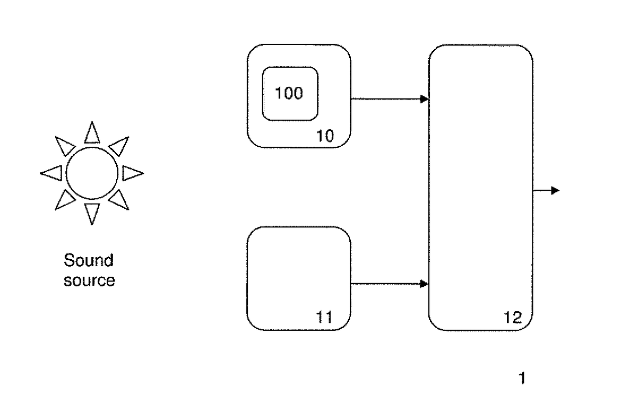
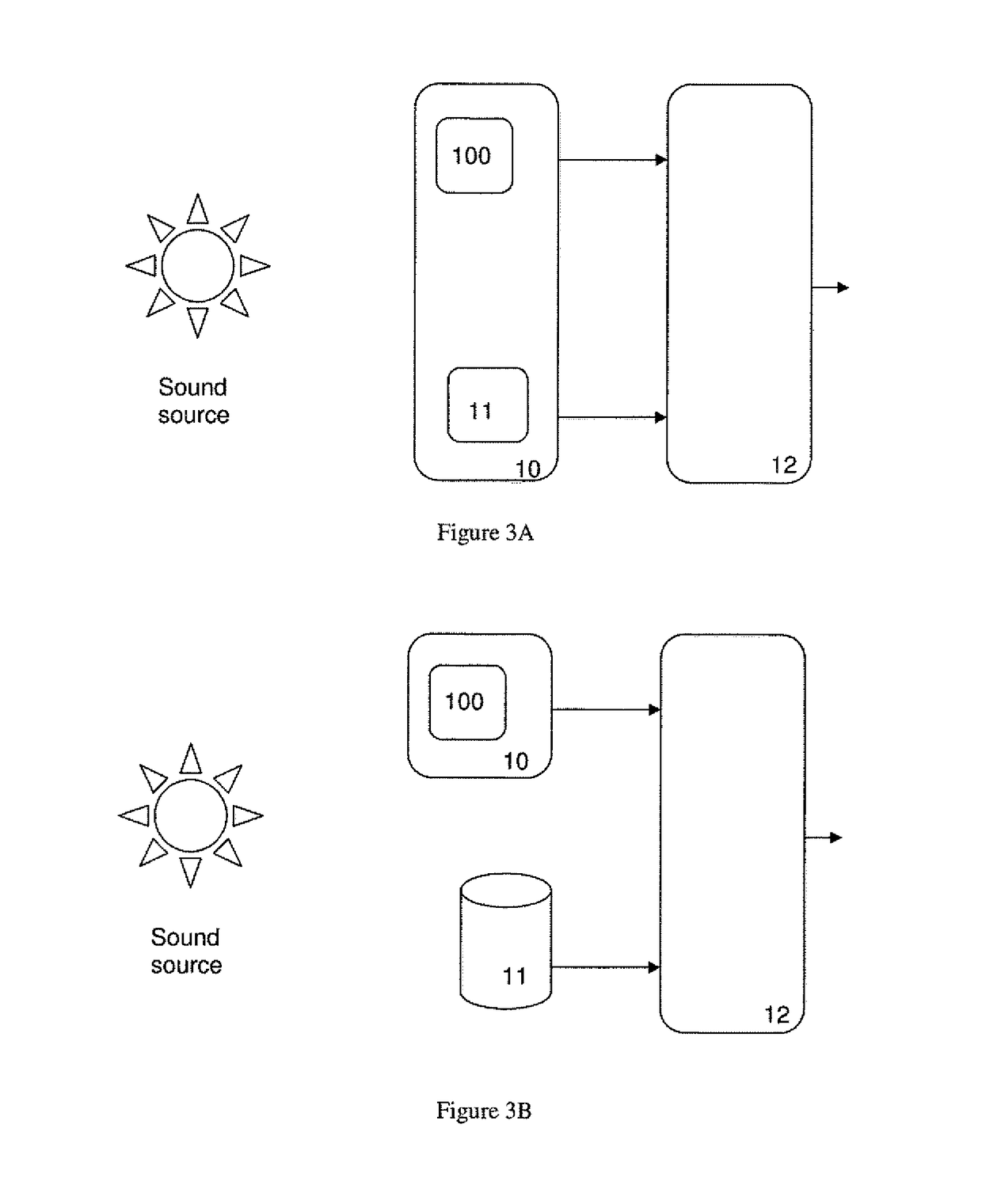
[0028]FIG. 1 is a block diagram of a system for localizing a sound source according to one embodiment of present invention. The system according to FIG. 1 is designated with 1 in its entirety. As shown in FIG. 1, the system 1 includes a movable unit 10, a motion tracking unit 11 and a processing unit 12. The movable unit 10 may be integrated with a microphone 100. The movable unit 10 is movable with freedom with respect to a sound source in a random path, for example in linear movement, in circular movement, in forward and backward movement, and so on. The motion tracking unit 11 is adapted for tracking the movement of the movable unit 10. This allows the flexibility of the selection of the movable unit path set by the operator.

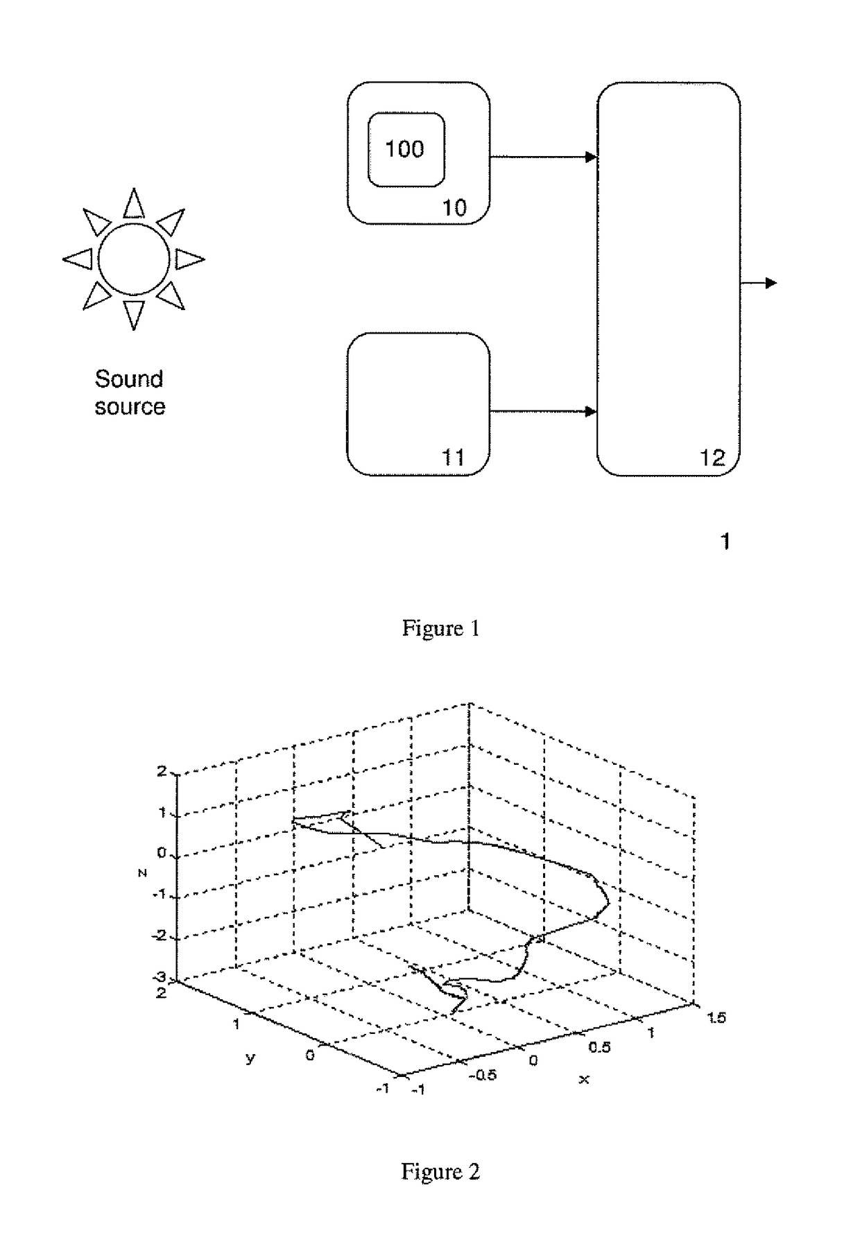
[0029]FIG. 2 illustrates a random movement of the movable unit according to one embodiment of present invention. The microphone 100 is adapted for collecting the sound wave that transmits from the sound source and arrives at the microphone 100, and thus gener...


PUM


Abstract

It is provided a system for localizing a sound source and a method therefor. The system includes a movable unit, being adapted for free movement and being integrated with a microphone; a motion tracking unit; and a processing unit, being adapted for receiving microphone signal and motion tracking unit signal and obtaining information on a direction from which sound from the sound source arrives using the microphone signal and motion tracking unit signal obtained during movement of the movable unit. By having the system and the method therefor, it is helpful for solving at least one of the technical problems: the complexity and a large volume of an acoustic camera for localization of a sound source; the restriction of the movement of the microphone in a sound source localization system.

Description

TECHNICAL FIELD[0001]The invention relates to the field of localization of a sound source, and more particularly to a system for evaluating the direction of a sound source and the method therefor.BACKGROUND ART[0002]Acoustic analysis is a method which today is often used for example in speech recognition however it is rarely ever used in industry application as a condition monitoring technique. The quality of acoustic monitoring is very much dependent on the background noise of the environment, which the machine is operated at. The effect of background noise can be mitigated by sound source localization. Sound source localization might be performed by acoustic camera.[0003]Sound analysis can be an important quality aspect of condition monitoring tool. When faults in machinery and plant installations occur, they can often be detected by a change in their noise emissions. In this way, acoustic camera makes the hearing procedure automated and more objective. Current technologies of aco...

Claims


Application Information

Patent Timeline
Patent Type & Authority Patents(United States)
IPC IPC(8): H04R29/00G01S3/809G01S3/803G01S3/802G01S5/20
CPCH04R29/004G01S3/809G01S3/8022G01S3/8032G01S5/20
Inventor ORMAN, MACIEJPAPE, DETLEF
Owner ABB (SCHWEIZ) AG
Learn More