Method for manufacturing a connector

a manufacturing method and connector technology, applied in the field of flexible containers for medical devices, can solve the problems of limiting the effort required for tightening, difficult manufacturing of such rings in the inner channel of the shaft, laborious for flexible and/or adhesive thermoplastic materials, etc., and achieve the effect of precise bead positioning and ideal positioning

Active Publication Date: 2017-08-29
TECHNOFLEX SA
View PDF1 Cites 0 Cited by
  • Summary
  • Abstract
  • Description
  • Claims
  • Application Information

AI Technical Summary

Benefits of technology

[0031]Furthermore, the method of the invention is particularly quick to implement and, therefore, allows industrial production of these connectors with low manufacturing costs.
[0040]Advantageously, a sealing membrane is formed inside said channel for ensuring the asepsis of the content of the container with which the connector will be assembled.
[0043]This sealing membrane also ensures ideal positioning of the annular recess in relation to the second electrode, and consequently the precise bead positioning inside the inner channel. Such a precise positioning of the bead is important for ensuring the impermeability of the trocar puncture needle / connector assembly.
[0053]Advantageously, since the inner channel of said conduit includes a breakable sealing membrane, the free end of said first tubular electrode has a blunt contact surface for placing it flush against said sealing membrane without tearing it.

Problems solved by technology

In addition to sealing the assembly, this contact also limits the effort required for tightening during the assembly of these elements.
The manufacture of such a ring in the inner channel of the shaft is, however, made difficult by the very nature of the materials used in the medical field.
Therefore, if the positioning of such a ring in the channel of a shaft formed from a relatively rigid thermoplastic material such as polypropylene (PP) is achievable, it becomes laborious for flexible and / or adhesive thermoplastic materials such as ethylene vinyl acetate (EVA) or EVA derivatives, in particular those compliant with the pharmacopoeia requirements.
Indeed, during the removal of the spindles, there is an extraction of material or the appearance of permanent deformations which require the withdrawal of the shaft formed in this manner.

Method used


Image

  • Method for manufacturing a connector
  • Method for manufacturing a connector
  • Method for manufacturing a connector

Examples


Embodiment Construction

[0065]It will firstly be noted that the figures are not to scale.

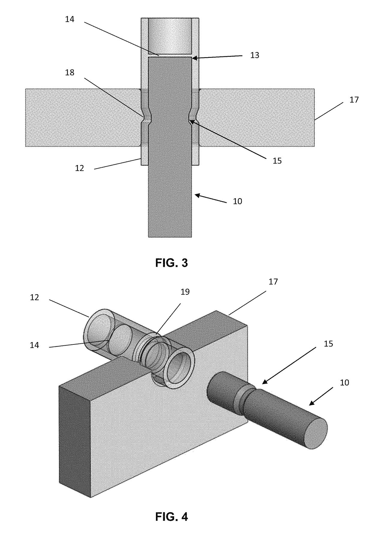
[0066]To produce a connector including a ring placed on the inside wall thereof defining a channel for a fluid to pass through, the operator obtains or manufactures, firstly, a tubular conduit 12 which does not have a ring projecting into the inner channel 11 thereof (FIGS. 5 and 6). This tubular conduit 12 advantageously includes a sealing membrane 14, the function of which will be described below.

[0067]This tubular conduit 12 can, for example, be produced using a known method of injecting a plastic, such as EVA, into a mould.

[0068]Once this tubular conduit 12 has been selected or manufactured, the operator can then produce one or more rings inside the channel thereof.

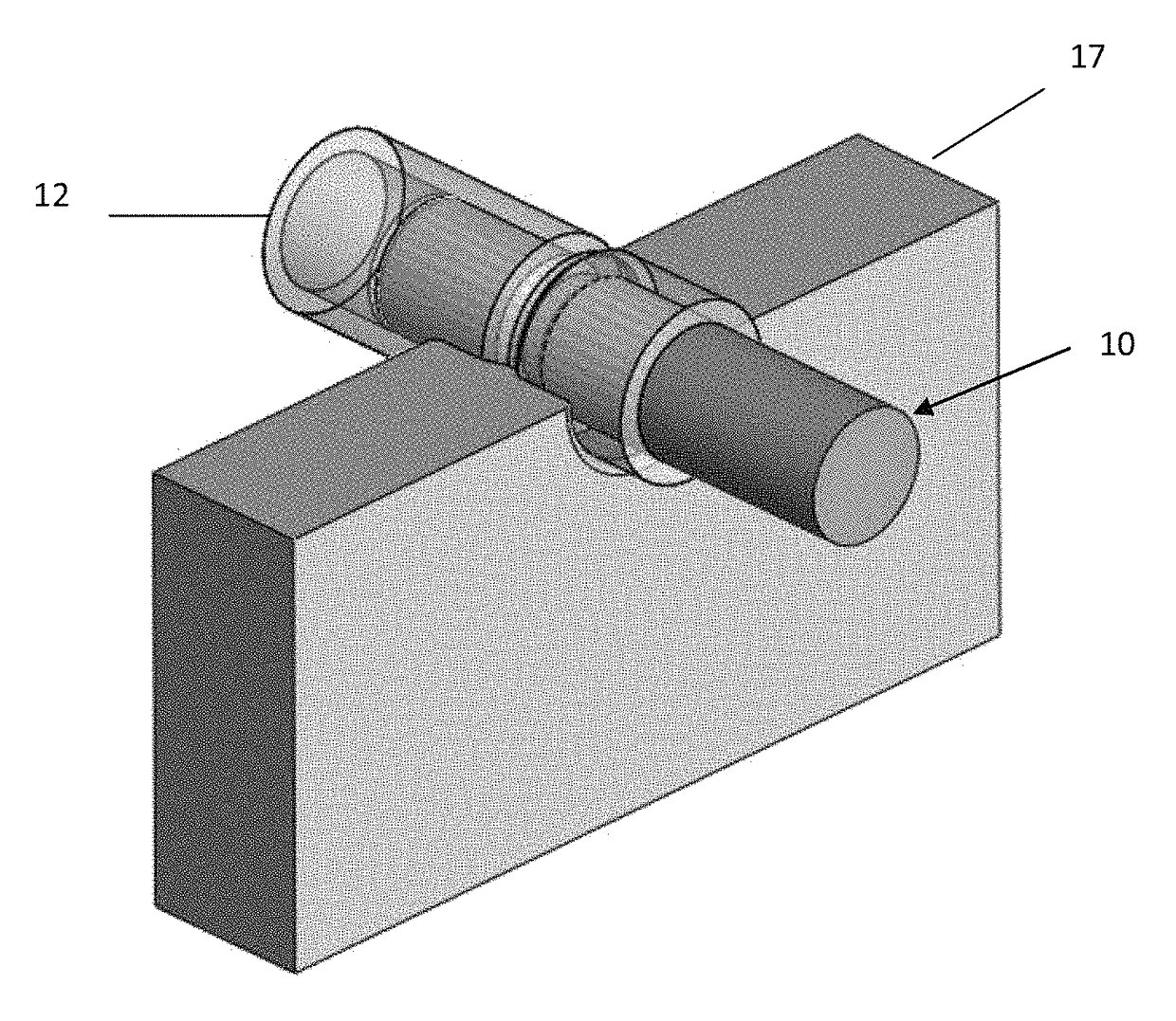
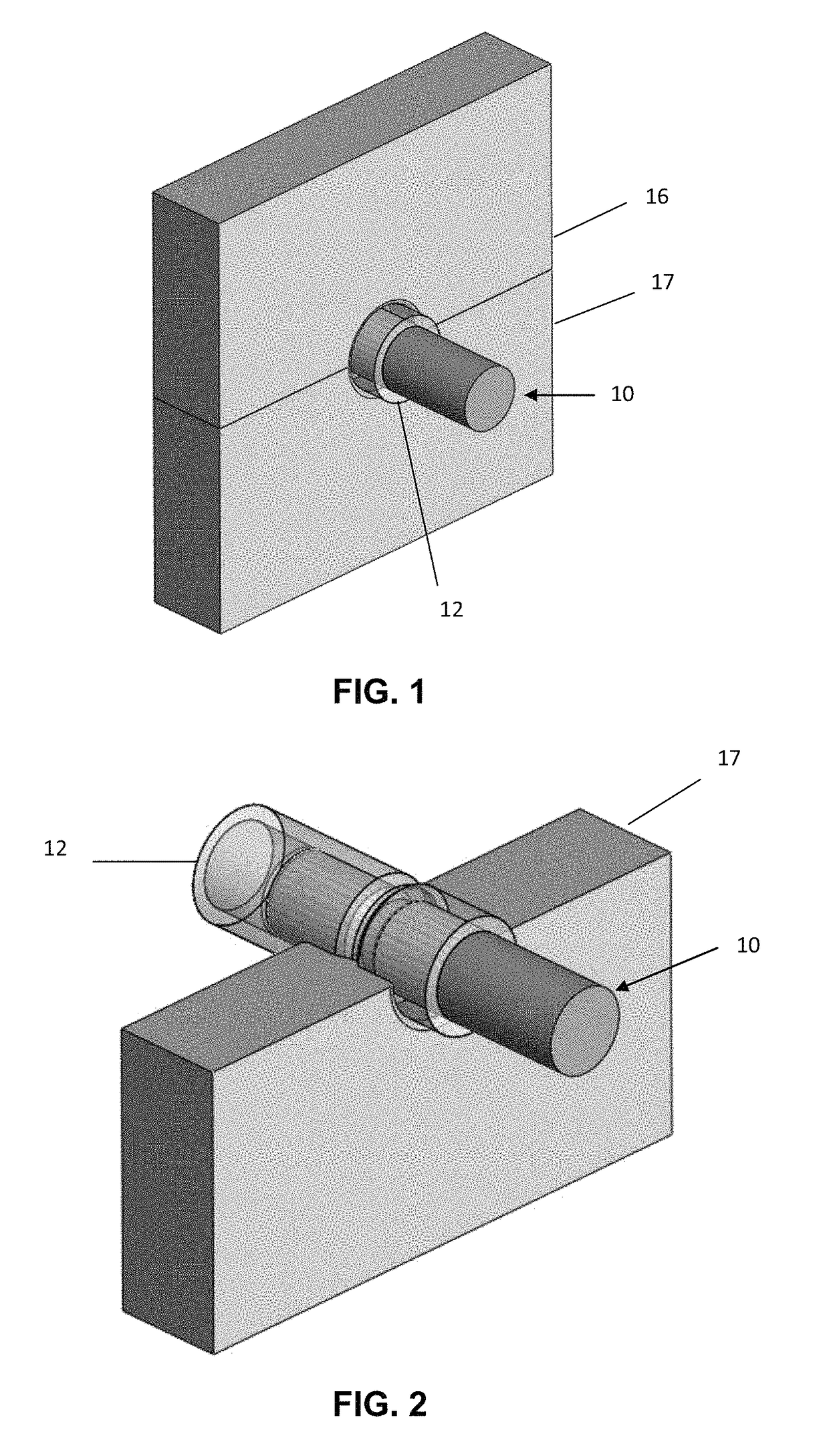
[0069]FIGS. 1-4 show an apparatus for manufacturing a connector according to a preferred embodiment of the invention.

[0070]This apparatus comprises a high-frequency electric generator (not shown) which can provide a high-frequency voltage. In this case, ...


PUM

PropertyMeasurementUnit
dimensionsaaaaaaaaaa
shapeaaaaaaaaaa
flexibleaaaaaaaaaa

Abstract

A method and apparatus for manufacturing a connector for a container for medical use intended to administer fluid, the connector including a main body defining an inner channel for fluid to pass through and at least one continuous or discontinuous bead, projecting inside the channel. The method includes:a) producing a tubular conduit with no bead projecting inside the channel,b) inserting at least partially into the tubular conduit a mandrel having, on its outer surface, at least one continuous or discontinuous annular recess, whose dimensions and shape correspond to those of a continuous or discontinuous bead to be formed in the inner channel,c) partially heating the tubular conduit, the part including at least the conduit portion placed at the at least one recess when the mandrel has been positioned in the tubular conduit, such that the material of the tubular conduit fills the at least one recess.

Description

BACKGROUND OF THE INVENTION[0001]Field of the Invention[0002]The present invention relates to flexible containers for medical use and particularly relates to a method for manufacturing a connector for such flexible bags.[0003]It also relates to an apparatus for implementing this method for manufacturing a connector.[0004]Technical Background[0005]Elements for accessing the content of a flexible bag intended to contain a liquid for medical use in order to fill and empty this bag are known.[0006]Such an access element generally takes the form of a shaft, which is formed by a tube portion being inserted between the two constituent inert plastic walls of the flexible bag and assembling the resulting assembly by binding together at least the peripheral edges of these walls.[0007]One end of this tube portion is in fluid communication with the interior volume of the flexible bag while the other end thereof is placed outside the bag.[0008]To establish liquid communication between the inside...

Claims


Application Information

Patent Timeline
Patent Type & Authority Patents(United States)
IPC IPC(8): B29C33/08A61M39/10B29D23/00B29C67/00
CPCB29C33/08A61M39/10B29C67/0022B29C67/0048B29D23/003
Inventor ANGOT, MAXIMECAPITAINE, FRANCOIS
Owner TECHNOFLEX SA
Why Eureka
Try Eureka