
Spinal marker system and methods of use

a marker system and spine technology, applied in the field of spine marker system and methods of use, can solve problems such as inability to transmit dy

Active Publication Date: 2017-09-05
NEHLS DANIEL
View PDF3 Cites 0 Cited by
  • Summary
  • Abstract
  • Description
  • Claims
  • Application Information

AI Technical Summary

Benefits of technology

The markers enable accurate identification of damaged discs and vertebral midline without puncturing healthy discs, reducing errors and the need for dye, while allowing for proper alignment of surgical instruments and implants.

Problems solved by technology

Advantageously neither the first nor the second penetration member include a cannula and are not suitable to transmit dye to the spine area.

Method used


Image

  • Spinal marker system and methods of use
  • Spinal marker system and methods of use
  • Spinal marker system and methods of use

Examples


Embodiment Construction

[0028]Embodiments of the present invention are described below. It is, however, expressly noted that the present invention is not limited to these embodiments, but rather the intention is that modifications that are apparent to the person skilled in the art and equivalents thereof are also included.

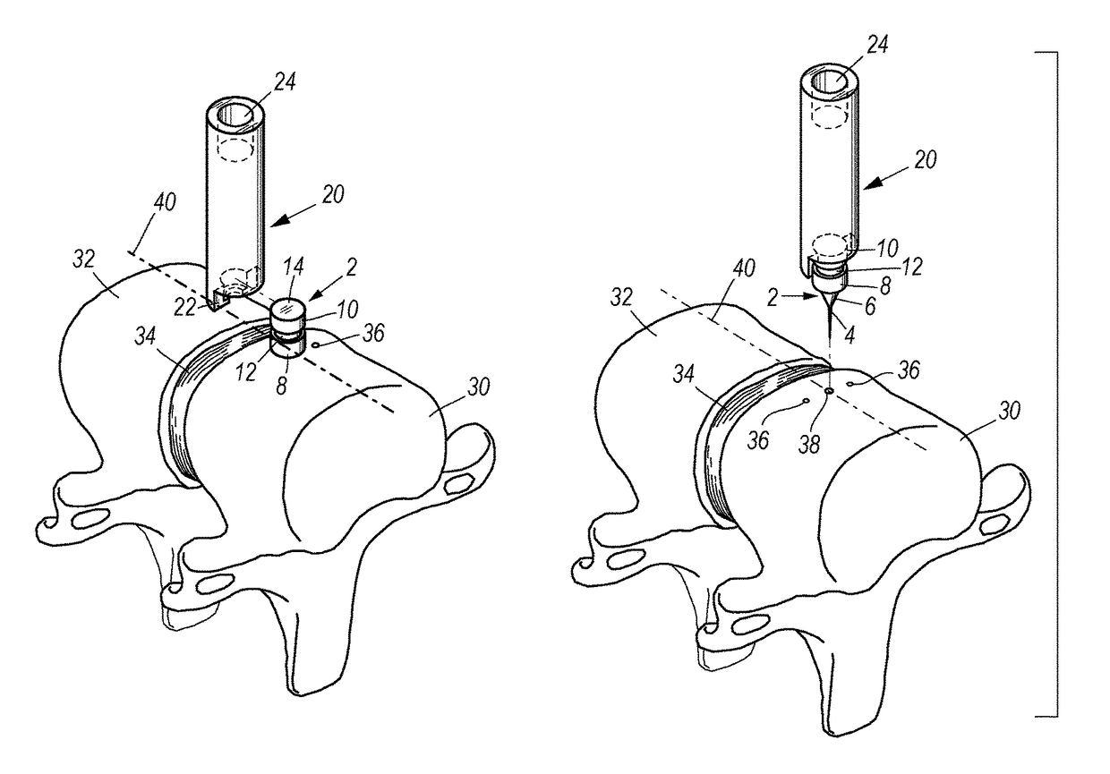
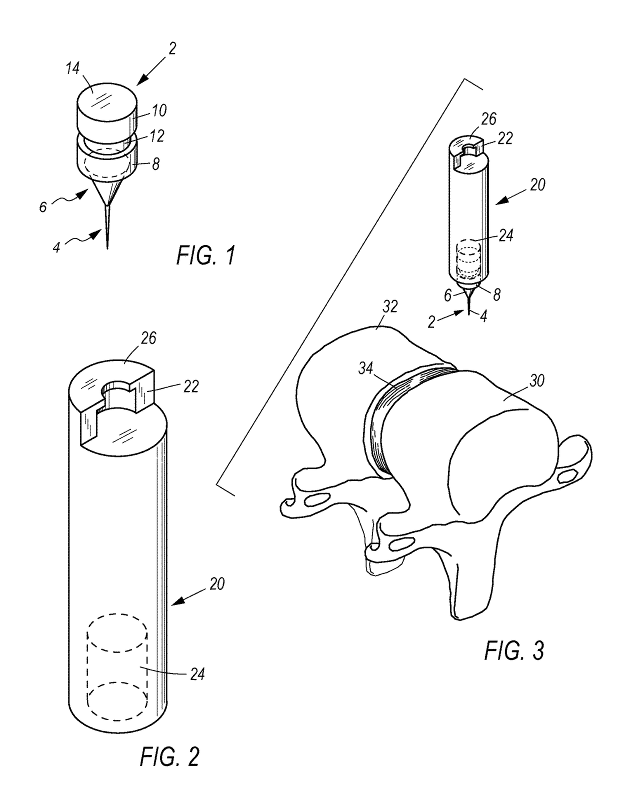
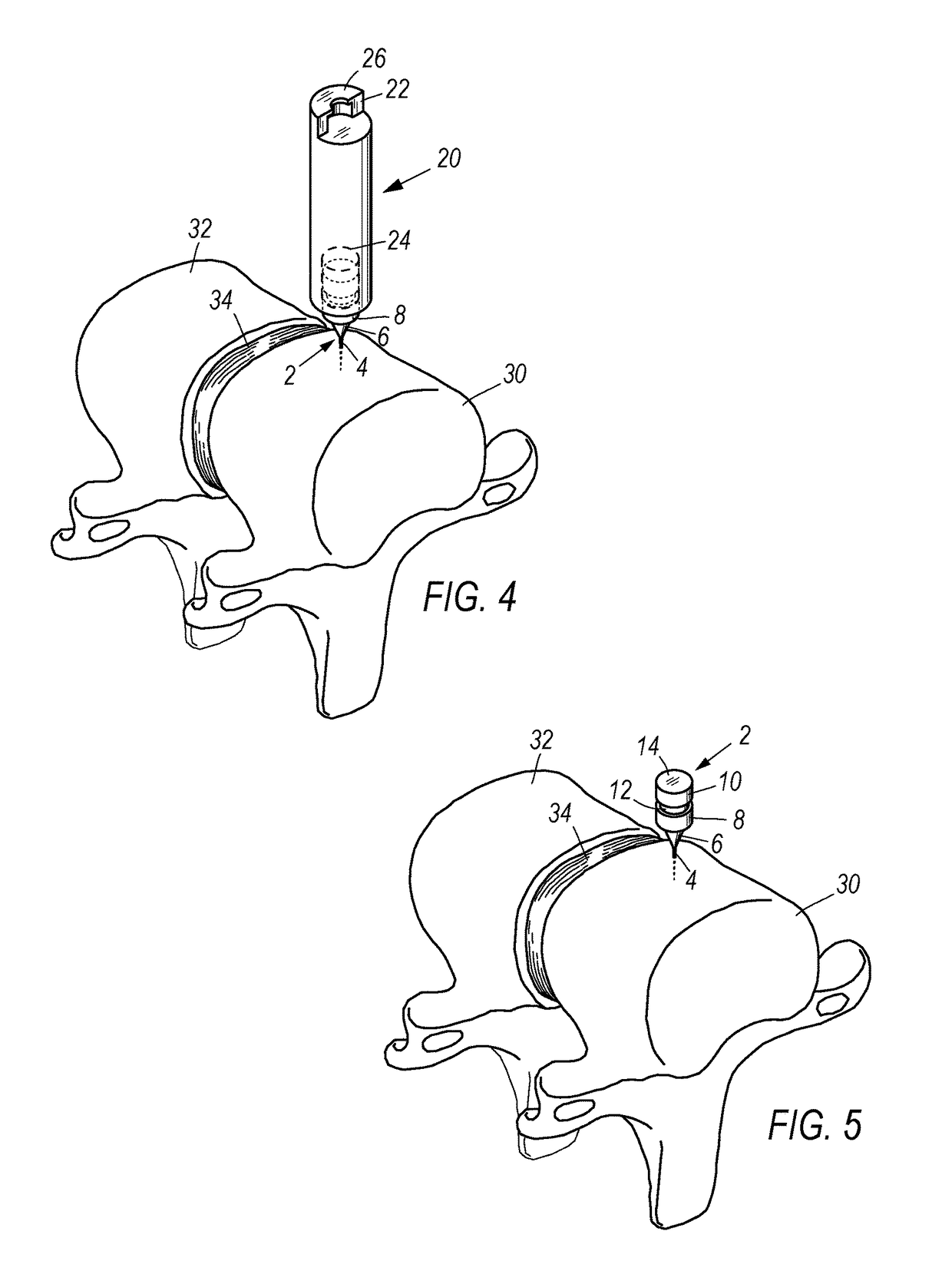
[0029]FIG. 1 depicts an example of a marker 2 that can be used with the systems and methods herein. The bottom portion of the marker 2 preferably includes a first penetrating member 4 that includes a downward facing sharp point, or apex, configured to pierce a patient's vertebral body 30. The first penetrating member 4 is preferably in the shape of a needle or a narrow, inverted cone. Advantageously, the apex of the first penetrating member 4 is configured to make a small test hole 36 in the vertebral body 30 when pressed in. Preferably, the first penetrating member 4 includes a base positioned at the opposite end of the apex that is coupled to or traverses through the apex of a second pe...


PUM


Abstract

Temporary, radiographically opaque, bone markers having first and second penetration members that are concentric with one another and are configured to pierce bone are provided herein. Bone markers can non-exclusively be used to help verify the correct surgical site along the vertebrae, locate the vertical midline, and as a fixed point for aligning surgical instruments. Insertion and extraction devices for use with the bone markers are also provided herein.

Description

CROSS-REFERENCE TO RELATED APPLICATIONS[0001]This application claims priority to and is a continuation to non-provisional U.S. Non-Provisional application Ser. No. 12 / 467,109 filed May 15, 2009, which is hereby expressly incorporated by reference in its entirety.FIELD OF THE INVENTION[0002]The embodiments herein relate to systems and methods useful in the medical field and are directed to temporarily marking the vertebrae in a patient in need. The assemblies and methods herein have many applicable uses including the ability to allow a surgeon to radiographically determine the location of a particular vertebral body. Additionally, the teachings herein can be used to locate a patient's vertebral midline, which is a useful determination for a variety of surgical procedures, non-exclusively including corpectomies and disectomies, for example.BACKGROUND[0003]When removing a disc from the spinal column, it is common practice for a surgeon to place a radiographically opaque needle into the...

Claims


Application Information

Patent Timeline
Patent Type & Authority Patents(United States)
IPC IPC(8): A61B17/16A61B17/17
CPCA61B17/1757
Inventor NEHLS, DANIEL
Owner NEHLS DANIEL
Learn More