Surgical imaging device

a surgical imaging and device technology, applied in the field of surgical imaging devices, can solve the problems of surgeons not being able to see the surgical site, difficult to maneuver, single view of the surgical site,

Inactive Publication Date: 2012-07-24
TYCO HEALTHCARE GRP LP
View PDF181 Cites 1021 Cited by
  • Summary
  • Abstract
  • Description
  • Claims
  • Application Information

AI Technical Summary

Benefits of technology

[0013]In accordance with another example embodiment of the present invention, a surgical imaging device is provided, wherein the surgical imaging device is configured to be inserted into a surgical site and wherein the surgical imaging device includes a plurality of prongs. Each one of the prongs has an image sensor mounted thereon. The image sensors provide different image data corresponding to the surgical site, thus enabling a surgeon to view a surgical site from several different angles.

Problems solved by technology

However, there are many types of surgical procedures in which the surgeon is not able to see the surgical site.
However, because of the small size of the incision, once one of these cameras is inserted through an incision and into a surgical site, it may be difficult to maneuver.
In addition, these cameras provide only a single view of the surgical site.
Another problem that is experienced by conventional surgical imaging systems is that they do not provide an image that is adequately stable.

Method used


Image

  • Surgical imaging device
  • Surgical imaging device
  • Surgical imaging device

Examples


Embodiment Construction

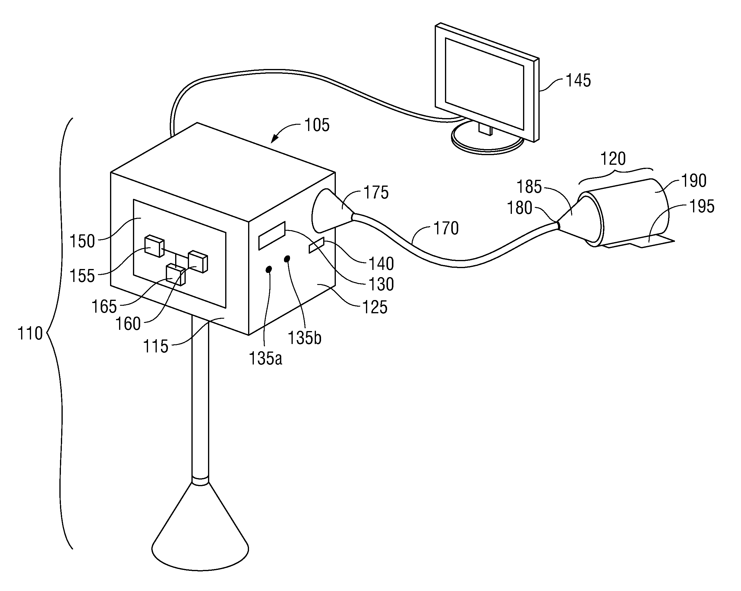
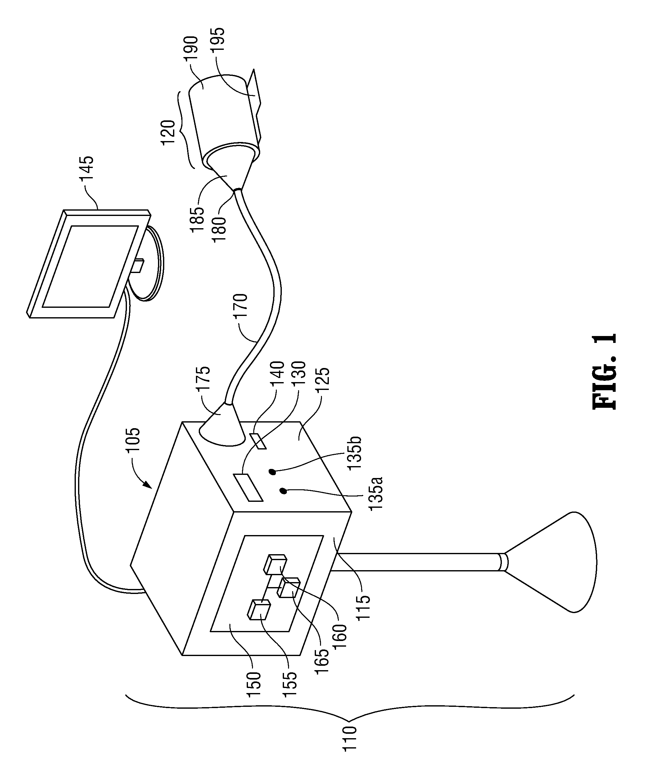
[0059]Referring now to FIG. 1, there is seen a surgical system 100. Surgical system 100 includes an electromechanical driver device 110 detachably coupled to a surgical attachment 120. Such an electro-mechanical driver device is described in, for example, U.S. patent application Ser. No. 09 / 723,715, entitled “Electro-Mechanical Surgical Device,” filed on Nov. 28, 2000, U.S. patent application Ser. No. 09 / 836,781, entitled “Electro-Mechanical Surgical Device, filed on Apr. 17, 2001, and U.S. patent application Ser. No. 09 / 887,789, entitled “Electro-Mechanical Surgical Device,” filed on Jun. 22, 2001, each of which is expressly incorporated herein in its entirety by reference. Electro-mechanical driver device 110 may include, for example, a remote power console (RPC) 105, which includes a housing 115 having a front panel 125. Mounted on front panel 125 are a display device 130 and indicators 135a, 135b. A connection slot 140 is also provided on front panel 125. Electro-mechanical driv...


PUM


Abstract

A surgical imaging device includes at least one light source for illuminating an object, at least two image sensors configured to generate image data corresponding to the object in the form of an image frame, and a video processor configured to receive from each image sensor the image data corresponding to the image frames and to process the image data so as to generate a composite image. The video processor may be configured to normalize, stabilize, orient and / or stitch the image data received from each image sensor so as to generate the composite image. Preferably, the video processor stitches the image data received from each image sensor by processing a portion of image data received from one image sensor that overlaps with a portion of image data received from another image sensor. Alternatively, the surgical device may be, e.g., a circular stapler, that includes a first part, e.g., a DLU portion, having an image sensor a second part, e.g., an anvil portion, that is moveable relative to the first part. The second part includes an arrangement, e.g., a bore extending therethrough, for conveying the image to the image sensor. The arrangement enables the image to be received by the image sensor without removing the surgical device from the surgical site.

Description

CROSS-REFERENCE TO RELATED APPLICATIONS[0001]This application relates to U.S. Patent Application Ser. No. 60 / 285,193, filed on Apr. 20, 2001, U.S. Patent Application Ser. No. 60 / 300,107, filed on Jun. 22, 2001, U.S. Patent Application Ser. No. 60 / 344,648, filed on Dec. 31, 2001, and U.S. Patent Application Ser. No. 60 / 352,726, filed on Jan. 30, 2002, each of which is expressly incorporated herein by reference in its entirety.[0002]This application also relates to U.S. patent application Ser. No. 09 / 324,452, filed on Jun. 2, 1999 and issued as U.S. Pat. No. 6,443,973, U.S. application Ser. No. 09 / 723,715, filed on Nov. 28, 2000, U.S. application Ser. No. 09 / 324,451, filed on Jun. 2, 1999 and issued as U.S. Pat. No. 6,315,184, U.S. application Ser. No. 09 / 351,534, filed on Jul. 12, 1999 and issued as U.S. Pat. No. 6,264,087, U.S. application Ser. No. 09 / 510,923, filed on Feb. 22, 2000 and issued as U.S. Pat. No. 6,517,565, U.S. application Ser. No. 09 / 510,927, filed on Feb. 22, 2000, ...

Claims


Application Information

Patent Timeline
Patent Type & Authority Patents(United States)
IPC IPC(8): A61B6/00
CPCA61B17/02A61B17/115A61B19/5212A61B1/05A61B17/0281A61B90/361
Inventor WHITMAN, MICHAEL P.MALINOUSKAS, DONALD
Owner TYCO HEALTHCARE GRP LP
Why Eureka
Try Eureka