
Surgical clamp assembly with electrodes

a technology of surgical clamps and electrodes, applied in the field of surgical clamps, can solve the problems of excessive size, clamps or inability to remove clamps, and achieve the effect of convenient application and removal

Inactive Publication Date: 2011-06-21
SANTILLI ALBERT N +1
View PDF20 Cites 1158 Cited by
  • Summary
  • Abstract
  • Description
  • Claims
  • Application Information

AI Technical Summary

Benefits of technology

"The present invention provides a surgical clamp assembly with improved heating capabilities for grasping and heating portions of a patient's body. The clamp has movable jaws that can be used for heating, severing, or cauterizing tissue. The clamp can be used in a variety of surgical procedures and is compact, reliable, and easy to apply and remove. The technical effects of the invention include improved surgical precision and reliability, as well as increased efficiency and ease of use for surgeons."

Problems solved by technology

A problem with existing cross clamps is their excessive size.
This is a significant factor in open-chest surgery, because the trauma caused by creating large openings in the chest wall often entails weeks of hospitalization and months of recuperation time.
A failure of the clamp or the inability to remove the clamp could have disastrous consequences for the patient.
An additional concern is that the referenced device employs a clamp made of metal that has no capability to heat tissue with which it comes in contact.

Method used


Image

  • Surgical clamp assembly with electrodes
  • Surgical clamp assembly with electrodes
  • Surgical clamp assembly with electrodes

Examples


second embodiment

A Second Embodiment

[0034]Referring now to FIGS. 4-6, an alternative surgical clamp assembly is indicated by the reference numeral 50. The assembly 50 is especially adapted for use during a gross thoracotomy, although it can be used for numerous other surgical procedures, if desired The clamp assembly 50 includes a clamp 52 and an actuator 54. The clamp 52 has a first jaw 56a and a second jaw 58a. A curved handle 56b is connected to the first jaw 56a. The handle 56b includes an upper, curved bar 56c at its end and a lower, curved bar 56d that is parallel to, but spaced from, the upper bar 56c. The second jaw 58a is similar to the arm 56a. A handle 58b is connected to the jaw 58a and includes an upper, curved bar 58c at its end and a lower, curved bar 58d that is parallel to, but spaced from, the upper bar 58c.

[0035]A plurality of teeth 60 are provided on the lower bar 56d, while a plurality of teeth 62 are provided on the upper bar 58c. The bars 56c, 58d do not have any teeth. As ca...

third embodiment

A Third Embodiment

[0042]Referring now to FIGS. 7-9, another surgical clamp assembly is indicated by the reference numeral 90. The assembly 90 is especially adapted for use during minimally invasive cardiac surgery, although it can be used for numerous other surgical procedures, if desired. The assembly 90 includes a clamp 92 and an actuator 94. The clamp 92 has a cylindrical base 96 with a bore therethrough. A first jaw 98 is rigidly connected to the cylindrical base. A second jaw 100 is pivotally connected to the cylindrical base 96. The connection is established by a slot 102 formed in the first jaw 98. A hinge pin 104 extends through the jaws 98, 100. Each of the jaws 98, 100 is provided with a plurality of electrodes 105 that form a part of a clamping surface intended to engage a portion of a patient's body. A pair of wires 106 extend from the electrodes 105 for connection to a source of electrical power (not shown). The electrodes 105 are attached to the respective jaws 98, 100...


PUM


Abstract

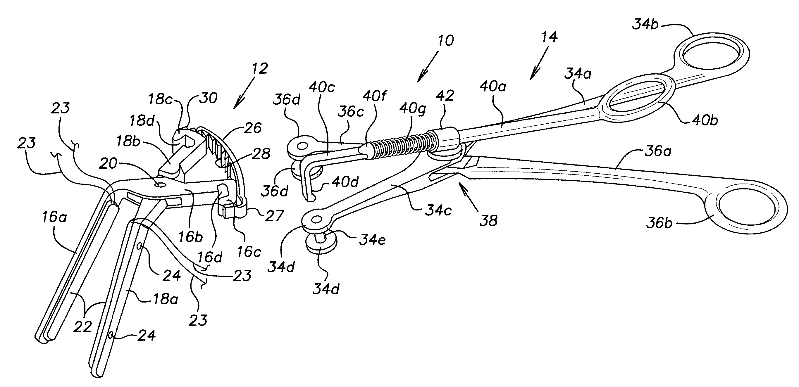
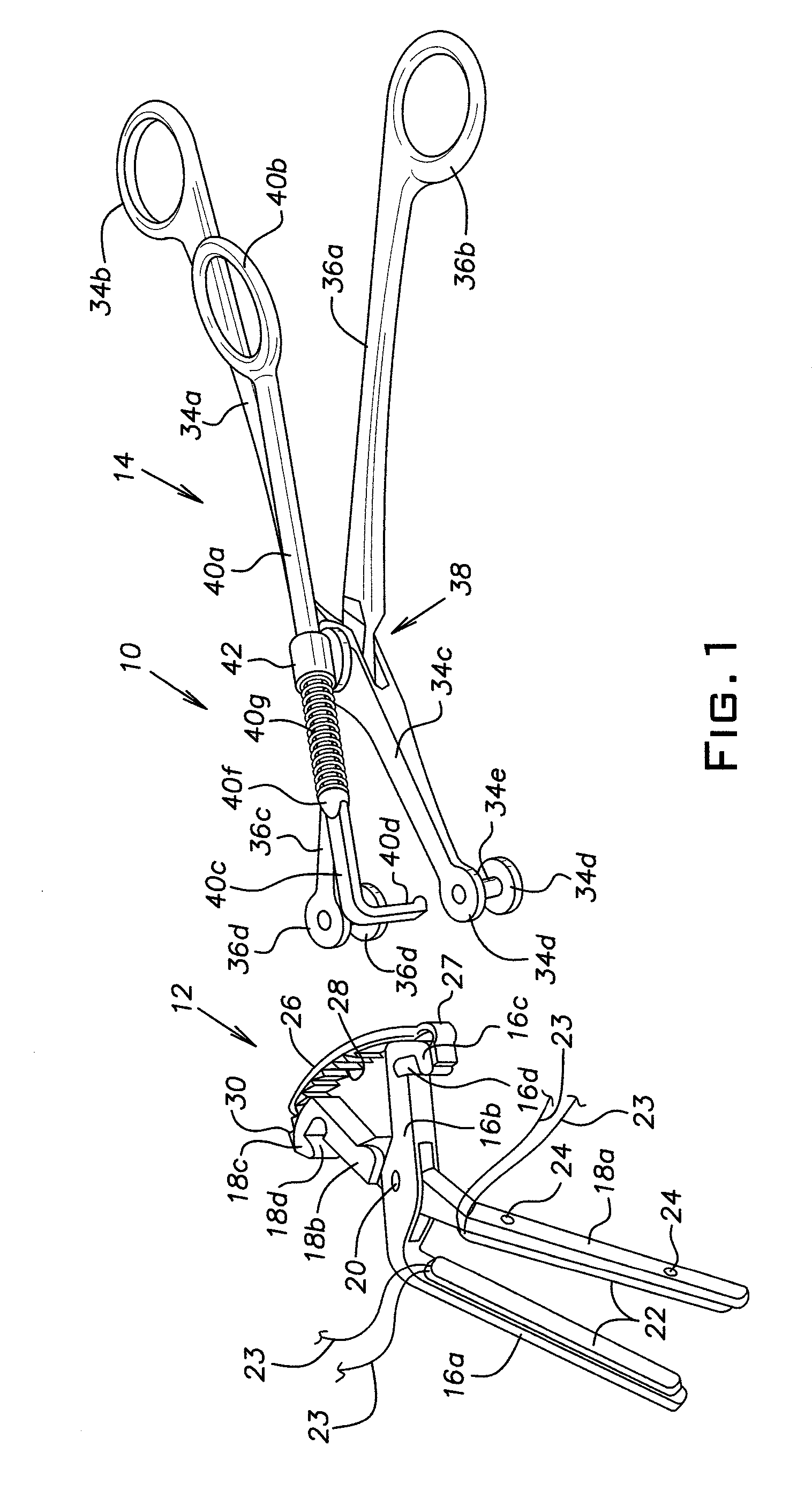
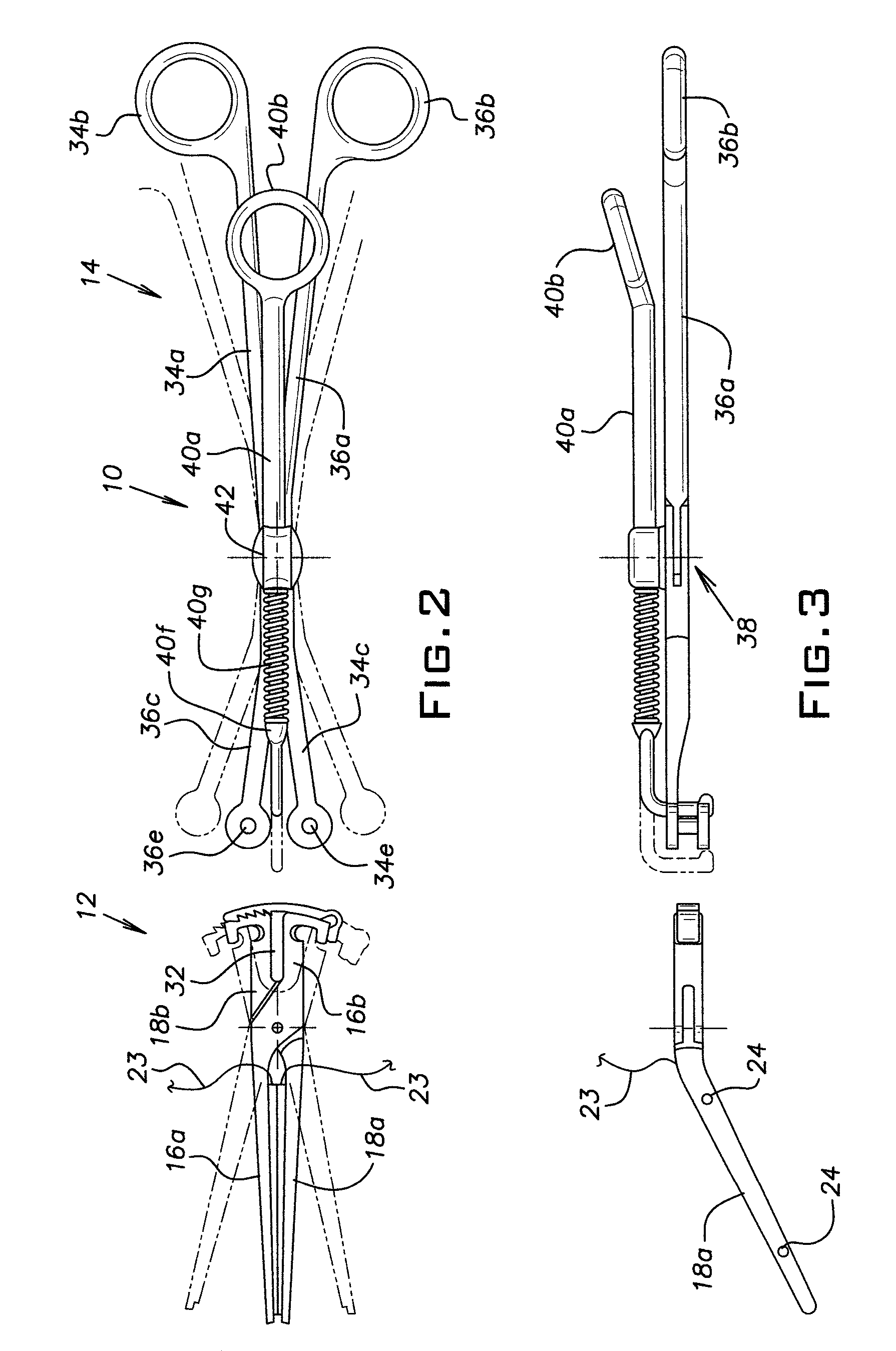
A surgical clamp assembly includes a clamp having movable jaws, each of which has a clamping surface for engaging a portion of a patient's body. An electrode forms a portion of the clamping surface of at least one of the jaws, the electrode being capable of heating, severing, or cauterizing the portion of the patient's body that is grasped by the clamp. If desired, the clamp assembly can be provided with a retainer that prevents the jaws from being opened accidently. The clamp assembly also can include an actuator that can be detached from the clamp and removed from the operative site, leaving the locked clamp in place. In this type of assembly, when it is desired to remove the clamp, the actuator can be reattached to the clamp and used to disengage the toothed retainer, and thereafter can be used to spread the jaws in order to permit the clamp to be removed.

Description

REFERENCE TO PENDING APPLICATION[0001]The present application is a continuation-in-part of application Ser. No. 10 / 631,052, filed Jul. 29, 2003, now U.S. Pat. No. 7,455,678, which is a division of application Ser. No. 09 / 781,000, filed Feb. 9, 2001, now U.S. Pat. No. 6,610,074, which claimed priority from provisional application Ser. No. 60 / 181,435, filed Feb. 10, 2000 by Albert N. Santilli.BACKGROUND OF THE INVENTION[0002]1. Field of the Invention[0003]The invention relates to clamps for surgical procedures and, more specifically, to a clamp assembly having the capability to heat tissue that is engaged by the clamp assembly.[0004]2. Description of the Prior Art[0005]The invention will be discussed in the context of cardiac surgery, although it is to be understood that the invention has applicability to a wide range of surgical procedures. During the course of cardiac surgery in which cardiac function is arrested, it is necessary to isolate the heart and coronary blood vessels from ...

Claims


Application Information

Patent Timeline
Patent Type & Authority Patents(United States)
IPC IPC(8): A61B18/14
CPCA61B18/1442A61B17/22012A61B18/085A61B2019/304A61B2018/1495A61B2090/034
Inventor SANTILLI, ALBERT N.PATEL, AMIT
Owner SANTILLI ALBERT N
Learn More