Plastic holder for anti-vibration fastening an elongated object

a technology of anti-vibration and elongation, which is applied in the field of holders, can solve the problems of limiting the possibilities of using the holders and correspondingly large installation space, and achieve the effects of low overall height, easy installation and low manufacturing cos

Active Publication Date: 2017-09-12
NEWFREY
View PDF18 Cites 1 Cited by
  • Summary
  • Abstract
  • Description
  • Claims
  • Application Information

AI Technical Summary

Benefits of technology

[0006]The object underlying the invention is to create a holder of the type mentioned at the beginning, which produces a vibration-insulating or damping attachment of an oblong object to a supporting element. The holder should also feature a low overall height and should permit an attachment of the oblong object or several oblong objects close to the fastening substrate. The holder must be easy to install and must ensure powerful withdrawal [sic] forces preventing detachment of the attached objects. The holder should also be inexpensive to manufacture and require a low amount of material for its manufacture.
[0009]In the holder according to the invention, the base part has an opening into which the retainer part can protrude with its apex region oriented toward the base part when it is moved relative to the base part as a result of vibrations. As a result, the retainer part can be situated very close to the base part without hindering the mobility of the retainer part relative to the base part and thus impairing the associated vibration insulation. The spatial proximity between the retainer part and the base part permits low space requirements for the installation of the holder and also a short distance between the oblong objects held by the holder and the substrate against which the base part rests and to which it is fastened.
[0010]The edge of the opening in the base part can also serve to limit the scope of the movement of the retainer part relative to the base part. This prevents the secured oblong objects from coming too close to the substrate. The support of the retainer part against the edge of the opening of the base part also provides a stabilization of the retainer part as the oblong objects are being inserted during installation and prevents the thin, flexible wall element from being excessively deformed during installation. By means of the opening in the base part, the retaining section of the retainer part, particularly in the apex region, can be reinforced by means of a rib for example in order to produce more powerful holding forces without negatively affecting the short distance between the base part and retainer part and therefore the space requirements of the holder.
[0011]In a preferred embodiment of the holder, the frame-shaped support section can have a rectangular frame with two longitudinal elements that extend parallel to the U-shaped cross-section of the retaining section and two transverse elements that connect them; the longitudinal elements and the transverse elements define the opening with a rectangular edge. Each of the longitudinal elements or transverse elements can be provided with a reinforcing rib in order to increase the rigidity of the frame. This frame-shaped configuration of the support section permits a rigid, stable embodiment of the base part so that a single bolt-accommodating opening is sufficient for attaching the base part to a substrate.
[0013]In order to simplify the retainer part, two adjacent retaining sections can be securely connected to each other to form a unit, which is connected to the base part by means of a respective thin, flexible wall element at each of the opposite ends. In this way, it is possible to reduce the number of thin, flexible wall elements, their attachments to the base part, and the amount of space they require.

Problems solved by technology

Therefore a correspondingly large amount of installation space is required, which limits the possibilities for using the holder.

Method used


Image

  • Plastic holder for anti-vibration fastening an elongated object
  • Plastic holder for anti-vibration fastening an elongated object
  • Plastic holder for anti-vibration fastening an elongated object

Examples


Embodiment Construction

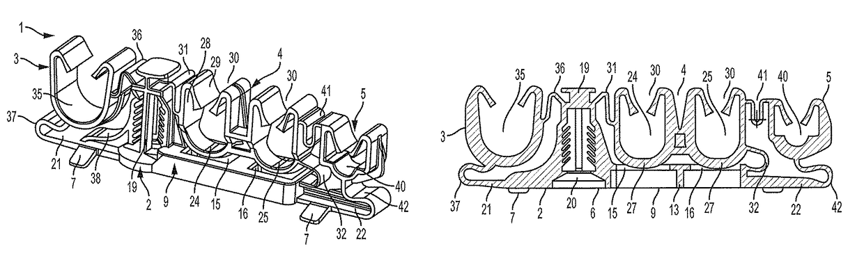
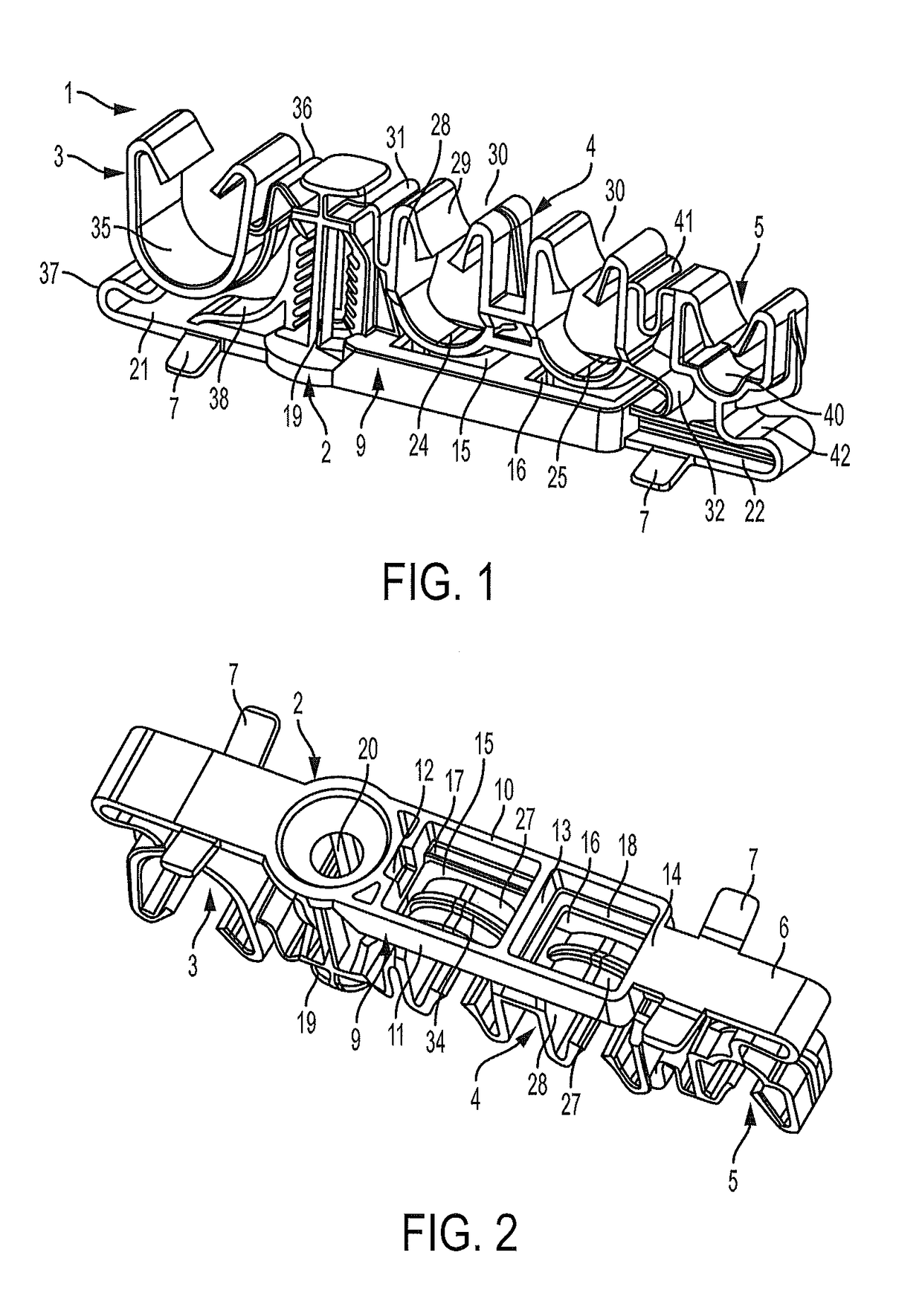
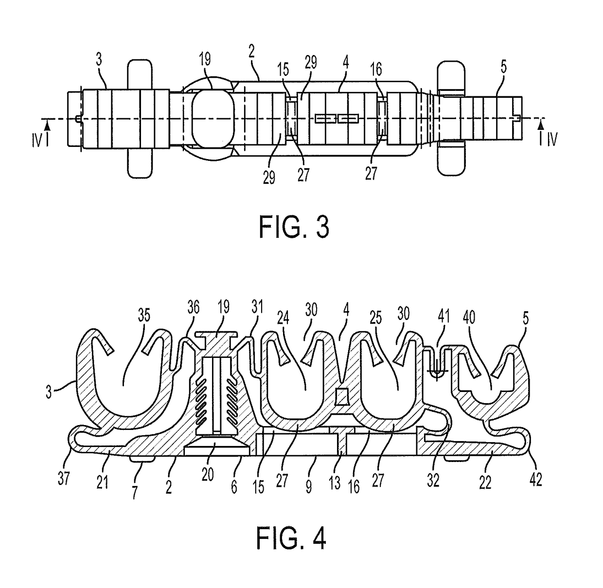
[0022]The holder 1 shown in the drawings is manufactured in the form of an injection-molded component made of plastic and includes an essentially rigid oblong base part 2 on which are arranged retainer parts 3, 4, 5 with retaining sections for receiving and holding oblong objects such as pipes or cables. The underside of the base part 2 oriented away from the retainer parts 3, 4, 5 is provided with a flat contact surface 6, which is designed to support the holder 1 on a substrate to which the holder 1 is fastened. Resilient fingers 7 that extend out laterally from the base part 2 protrude downward with their free ends beyond the plane of the contact surface 6 and should produce a resilient, play-free support of the holder 1 on the substrate supporting it.

[0023]In its middle region, the base part 2 is embodied in the form of a rectangular frame 9 that has two parallel longitudinal elements 10, 11 and transverse elements 12, 13, 14 connecting them. The transverse element 13 connects t...


PUM


Abstract

A holder made of plastic for vibration-insulating attachment of an oblong object such as a pipe or the like to a vehicle includes a base part with a bolt-accommodating opening and retainer parts that have a U-shaped retaining section with a recess that has a hollow inner surface and an insertion opening at which a resilient retaining finger is provided, which is able to hold an oblong object in the recess. The retainer parts are connected to the base part by means of thin, flexible wall elements. The base part has a frame with openings and the apex regions of the retaining sections on the side opposite from the insertion opening can move into these openings.

Description

CROSS-REFERENCE TO RELATED APPLICATION[0001]This application claims priority from German Patent Application No. DE 102014114275.6, filed on Oct. 1, 2014, the disclosure of which is incorporated herein by reference.BACKGROUND OF THE INVENTION[0002]The invention relates to a holder made of plastic for vibration-insulating attachment of an oblong object such as a pipe or the like to a vehicle, having a base part in which a bolt-accommodating opening is provided and having a retainer part that is integrally formed onto the base part and has a retaining section formed by a wall with a U-shaped cross-section, with a recess that is suitable for accommodating the oblong object and has a hollow inner surface and an insertion opening oriented away from the base part; a resilient retaining finger that protrudes into the recess is provided at the insertion opening and is able to hold the oblong object in the recess; the retainer part is connected to the base part by means of one or more thin, f...

Claims


Application Information

Patent Timeline
Patent Type & Authority Patents(United States)
IPC IPC(8): F16L3/22F16L3/227F16L3/13H02G3/32F16L55/035F16L3/223B60R16/02B60R16/00F16L3/237F16B15/00F16B45/00F16L3/00F16L3/08F16L3/12
CPCB60R16/00B60R16/0215F16L3/13F16L3/223F16L3/227F16L3/237F16L55/035H02G3/32
Inventor STAU, BASTIANSCHLIESSNER, LOTHAR
Owner NEWFREY
Why Eureka
Try Eureka