
Post assembly

a technology of post assembly and barrier system, which is applied in the direction of roads, traffic signals, roads, etc., can solve the problems of high peak load being transferred to the anchor bolt, large plates may be difficult to accommodate in car park environments, and the system strength is typically relatively weak, so as to reduce the pullout force

Active Publication Date: 2017-09-12
SAFE DIRECTION
View PDF9 Cites 3 Cited by
  • Summary
  • Abstract
  • Description
  • Claims
  • Application Information

AI Technical Summary

Benefits of technology

[0009]Preferably, the at least one aperture is located remote from the hinge region to reduce pullout forces on the associated fastener when the post pivots relative to the footing.

Problems solved by technology

Despite the posts being relatively strong in their own right the strength of the system is typically relatively weak as its capacity is limited by the pullout resistance of anchor bolts that secure the base plated posts to the underlying ground / concrete slab.
Rigid post systems absorb the full force of the impact with little deflection resulting in a high peak load being transferred to the anchor bolts.
However, larger plates may be difficult to accommodate in a car park environment.
The material costs of large base plates can be prohibitive and holes drilled for multiple fastening bolts may compromise the structural integrity of an underlying concrete slab, which could be of particular concern if the slab forms an elevated floor in a multi-level car park.

Method used


Image

  • Post assembly
  • Post assembly
  • Post assembly

Examples


Embodiment Construction

[0039]Throughout the specification and drawings, like parts will be denoted with like reference numerals.

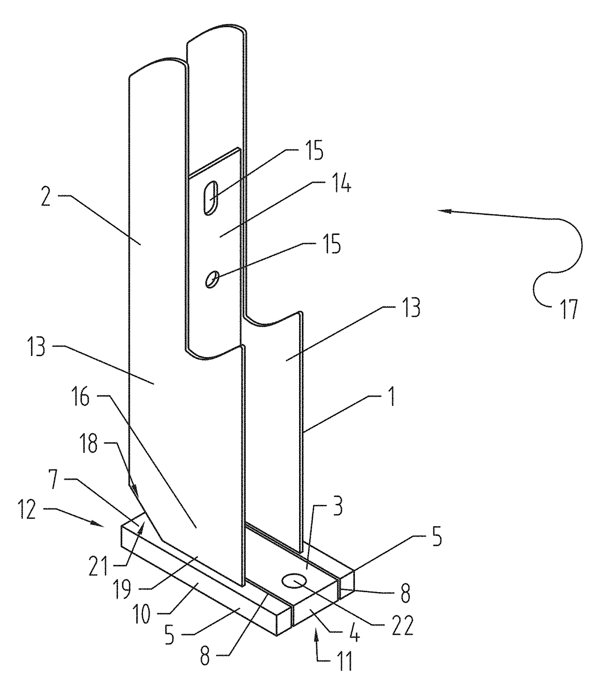
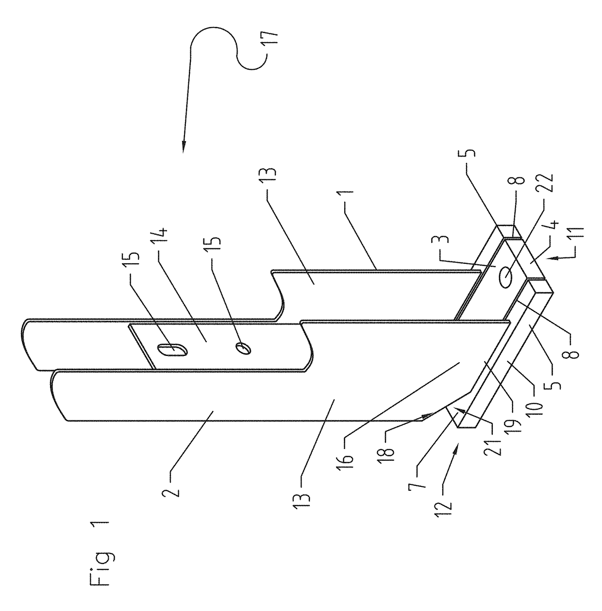
[0040]Referring firstly to FIG. 1, a post assembly 1 includes a post 2 and a footing 3.

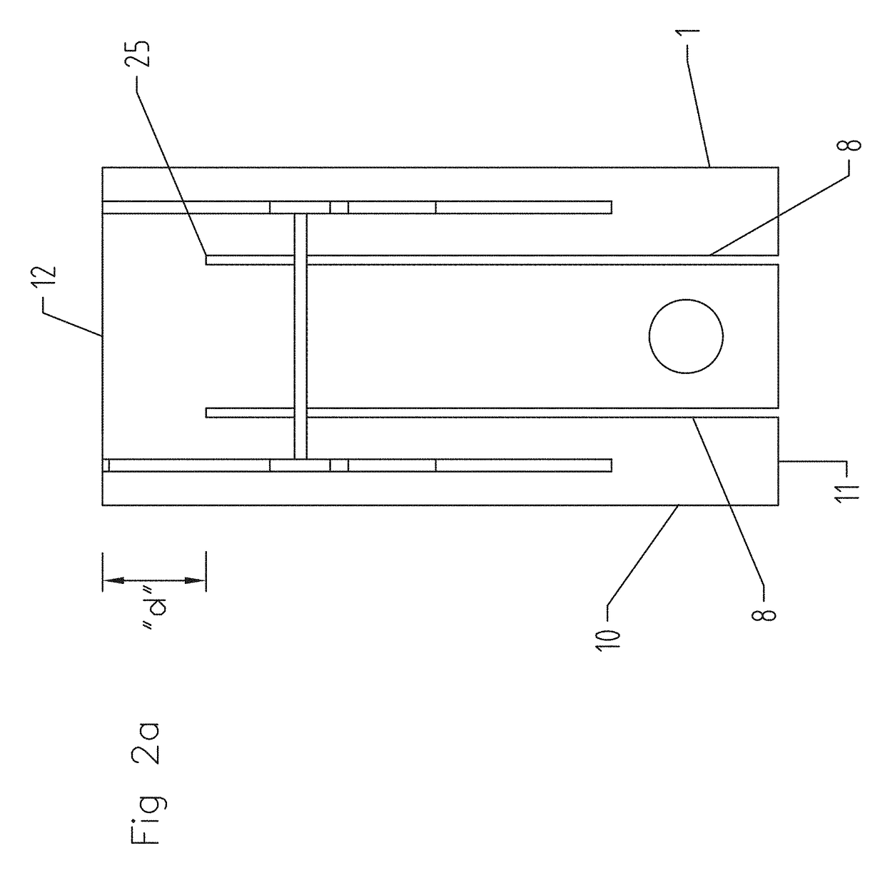
[0041]The footing 3 includes a base pad 4 connected to first and second lever arms 5 via a hinge region 7. The lever arms 5 are positioned on opposed sides of the base pad 4 and are separated from the base pad 4 by elongate slots 8 in order to be free to pivot about the hinge region 7.

[0042]The lever arms 5 and the footing 3 are formed as a single base plate 10, so that the lever arms 5 and footing 3 are substantially co-planar. The slots 8 are preferably machined into the plate 10 to extend from a front side 11 of the plate 10, toward a rear side 12 of the plate 10. However, the slots 8 terminate short of the rear side 12 in order to define the hinge region 7 that connects the base pad 4 and lever arms 5, 6.

[0043]The post 2 is formed of two opposed side members 13 arranged in a parallel front ...


PUM


Abstract

A post assembly for absorbing impact from a vehicle including a footing, an upright post and a hinge region to allow the post to plastically deform relative to the footing. The post is preferably fixed to a lever arm that is connected to the footing via the hinge region, the lever arm and post pivoting away from the footing under load, The lever arm, footing and hinge region are preferably formed from a common base plate. The invention also relates to barrier system that includes multiple post assemblies, and a barrier supported between respective posts of the assemblies.

Description

RELATED APPLICATION[0001]The present application is a U.S. National Phase Application of International Patent Application No. PCT / AU2014 / 050217, filed on Sep. 8, 2014, which claims priority from Australian Patent Application No. 2013234430, filed on Sep. 30, 2013, the contents of which are incorporated in entirety by reference.FIELD OF THE INVENTION[0002]The present invention relates to a post assembly for a barrier system particularly but not exclusively a car park guardrail system.BACKGROUND OF THE INVENTION[0003]Traditional base plated posts used in a guardrail system are manufactured from relatively strong rigid materials such as steel. Despite the posts being relatively strong in their own right the strength of the system is typically relatively weak as its capacity is limited by the pullout resistance of anchor bolts that secure the base plated posts to the underlying ground / concrete slab. Rigid post systems absorb the full force of the impact with little deflection resulting ...

Claims


Application Information

Patent Timeline
Patent Type & Authority Patents(United States)
IPC IPC(8): E01F15/04E01F15/14E01F9/646
CPCE01F15/0438E01F15/0415E01F15/0461E01F15/0476E01F15/146E01F9/631
Inventor WALLACE, HAYDEN
Owner SAFE DIRECTION
Learn More