Frac plug body

a plug body and frac technology, applied in the field of frac plugs, can solve the problems of inability to discharge fluid, inability to remove perforated or other tools, etc., and achieve the effect of sufficient flow area

Active Publication Date: 2017-09-12
BAKER HUGHES HLDG LLC
View PDF17 Cites 5 Cited by
  • Summary
  • Abstract
  • Description
  • Claims
  • Application Information

AI Technical Summary

Problems solved by technology

Initially the toe of the well is perforated and fractured.
If a sealing ball has already seated and could not be removed therefrom, or if a bridge plug was utilized, such fluid flow would not be possible and the perforating or other tool would have to be lowered by other means.
The tubular mandrel is preferably made of readily drillable materials but in order to meet its structural requirements when the frac plug is set winds up being a significant cost driver in the cost of fabrication of the frac plug assembly.

Method used


Image

  • Frac plug body
  • Frac plug body
  • Frac plug body

Examples


Embodiment Construction

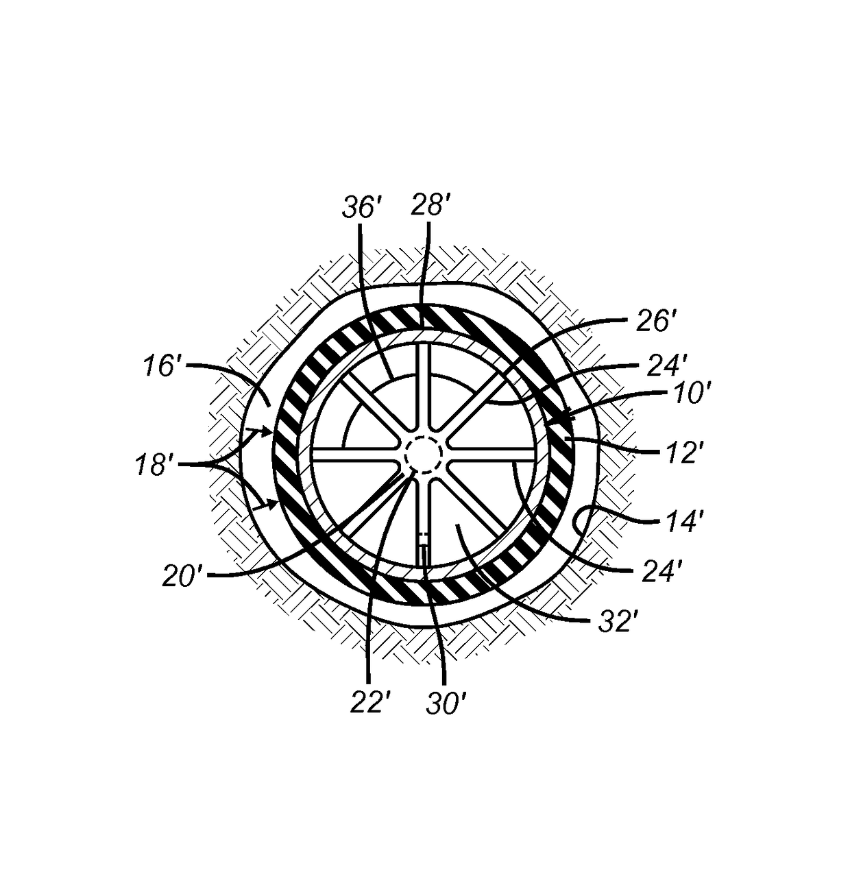
[0017]The present invention seeks to replace the thick wall of a tubular mandrel that is usually made of a filament wound composite structure with an alternative structure that meets the performance criteria but is significantly more economical to produce. The performance criteria include the ability to allow flow through the mandrel so that a ball or plug can be rapidly deployed to a seat in horizontal or near horizontal completions. The structure has to resist collapse from the set seal of the frac plug and the material for the assembly has to be readily drillable so that the frac plugs can all be milled up and the cuttings circulated to the surface after the fracturing of the zone of interest is concluded. Since the focus of the invention is on the mandrel structure of an otherwise known frac plug structure as described above, the drawings will illustrate the mandrel structure only, with those skilled in the art recognizing that the mandrel assembly of the present invention is in...


PUM


Abstract

A frac plug mandrel assembly has an inner core that permits flow that is surrounded by a thin wall tube that distributes compressive loading, such as that applied by the set sealing element to the core. The core is a cylindrically shaped insert for inside the tube and allows flow until a ball or plug is landed on a seat to close off the flow through the core. The core can have a star pattern with a series of radially extending segments from a solid hub or a cylindrical shape of a honeycomb or other porous structure that has the requisite strength to resist collapse from compressive loading of the set sealing element while still allowing sufficient flow area for fluid displacement.

Description

FIELD OF THE INVENTION[0001]The field of the invention is frac plugs and more particularly plugs that have a more economical mandrel design with a flow through structure that has the ability to withstand compressive collapse loads from the surrounding set seal.BACKGROUND OF THE INVENTION[0002]Fracturing is commonly done is horizontal or nearly horizontal completions. Initially the toe of the well is perforated and fractured. After that a frac plug with a perforating gun are run together and the plug is set with a known setting tool secured to it which then releases from it. The gun is released from the set plug and shot. The previously fractured zone at the toe of the well is isolated by pumping a ball to the set frac plug after the gun has been tripped out. The frac plug typically has a passage through a tubular mandrel and a seat for a ball or a dart to land on and obstruct the zone below that has already been fractured. The next zone above the toe is then fractured and the proces...

Claims


Application Information

Patent Timeline
Patent Type & Authority Patents(United States)
IPC IPC(8): E21B33/12E21B33/129E21B43/26
CPCE21B33/12E21B33/1294E21B43/26
Inventor KING, JAMES G.O'MALLEY, EDWARD J.
Owner BAKER HUGHES HLDG LLC
Why Eureka
Try Eureka