Electric power station

a technology of electric power station and solar cell, applied in the direction of instruments, base element modifications, transportation and packaging, etc., can solve the problem that solar cells only produce electrical energy, and achieve the effect of increasing the environmental aesthetics of the system

Active Publication Date: 2017-09-19
KLEPFER HLDG
View PDF10 Cites 5 Cited by
  • Summary
  • Abstract
  • Description
  • Claims
  • Application Information

AI Technical Summary

Benefits of technology

[0011]With computer control, this hybrid energy production and management system both stores potential energy in batteries, and generates electricity based upon demand, the demand evaluated and distributed in real time by the system computer and controls. This energy producing system provides an energy source that may be utilized even when no electricity is available to recharge the batteries. For example, a solar cell array may be utilized as one source to charge the batteries, but solar cells only produce electrical energy when there is sufficient sunlight. Thus, the energy generated by the system of the present invention may be engaged when sunlight is deficient or not available. Note that electricity from the grid, a solar array, a fuel fired generator, or other conventional means may be employed as a backup system to maintain the charge of the batteries. However, in a stand-alone or solitary configuration of the present invention, the backup could be limited to a solar array as one source providing independence from the electrical distribution grid. As a byproduct, use of a solar array increases the environmental aesthetics of the system.

Problems solved by technology

For example, a solar cell array may be utilized as one source to charge the batteries, but solar cells only produce electrical energy when there is sufficient sunlight.

Method used


Image

  • Electric power station
  • Electric power station
  • Electric power station

Examples


Embodiment Construction

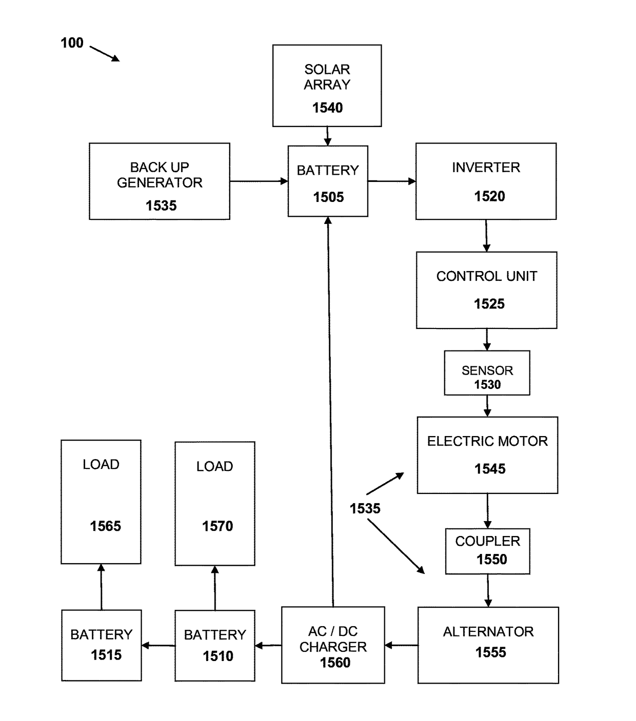
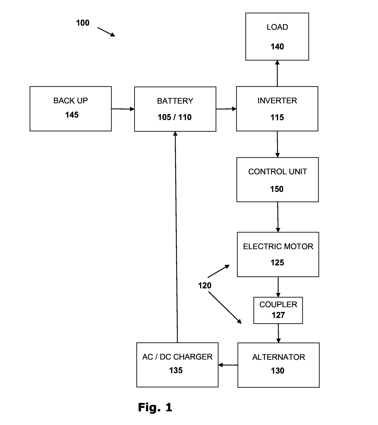
[0046]The present invention provides an environmentally sensitive electrical power station that may be scaled to service a plurality of loads, including but not limited to industrial, commercial or residential electrical demand with the ability to grow with increased electrical demands of the business or residence with minimal or no outside power source. The EPS power system of the present invention produces electrical current (AC or DC) to power an electric motor that in turn engages an electrical generator to produce electrical power distributed to a plurality of batteries to service a load and use a portion of that generated electricity to recharge the battery, and a method of production and distribution of the energy produced there from.

[0047]The invention preferably comprises an electrical power generation apparatus 100 converting stored chemical energy in a battery 105 into mechanical motive energy to cause rotation of an electric generator 120 to produce electricity.

[0048]In ...


PUM


Abstract

The apparatus and method of the present invention is a closed loop system that obtains, stores and transfers motive energy. Preferably, the majority of the electricity generated by the method of the present invention is utilized to service a load or supplied to the grid. A portion of the electric power produced is used to recharge the batteries for subsequent use of the electric motor. The system of the present invention controls and manages the battery power by controlling the charging and discharging of the battery reservoir via a series of electrical and mechanical innovations controlled by electronic instruction using a series of devices to analyze, optimize and perform power production and charging functions in sequence to achieve its purpose.

Description

BACKGROUND[0001]The present invention relates generally to an electric power station (hereinafter, EPS). Particularly to a regenerative hybrid energy storage and conversion apparatus and method to produce and distribute electrical energy. More particularly, to an apparatus and method that utilizes available stored energy to supply an electric demand and senses where the demand is greatest to preferentially supply that demand. More particularly, the present invention relates to a hybrid power storage and electrical generation apparatus where potential energy is produced and stored by one or more methods to be subsequently converted to mechanical energy to rotate an electric generator. More particularly, the present invention comprises an apparatus that regenerates and stores electrical energy as chemical potential energy in a battery to be transferred into mechanical energy on demand for the purpose of rotating an electrical generator to service a load and use a portion of that gener...

Claims


Application Information

Patent Timeline
Patent Type & Authority Patents(United States)
IPC IPC(8): H02J7/00H02J3/32H02J7/14G01R31/36G01R1/20G01R27/08H02J7/35
CPCH02J7/0068G01R1/203G01R27/08G01R31/36G01R31/3658H02J3/32H02J7/0022H02J7/1415H02J7/0047H02J7/35Y02T10/7005Y02T10/7055Y10T307/336Y02T10/70H02J7/0013H02J7/0048H02J3/322G01R31/396G01R31/3648
Inventor MITRI, GEORGEKLEPFER, DONSCHMIDT, DARRELL
Owner KLEPFER HLDG
Why Eureka
Try Eureka