Process for the formation of a stack of superposed metallic laminations

a technology of superposed metallic lamination and stacking, which is applied in the direction of magnetic circuit rotating parts, manufacturing stator/rotor bodies, and shape/form/construction of magnetic circuits, etc. it can solve the problems of presenting a fragile axial locking stability, and reducing the useful life of the insertion clamp, so as to increase the manufacturing cost of the lamination, the effect of reliable and efficient axial and rotational locking

Active Publication Date: 2017-09-19
EMBRACO IND DE COMPRESSORES E SOLUCOES EM REFRIGERACAO LTDA
View PDF19 Cites 0 Cited by
  • Summary
  • Abstract
  • Description
  • Claims
  • Application Information

AI Technical Summary

Benefits of technology

[0010]It is an object of the present invention to provide a metallic lamination, to be placed over other metallic lamination, upon the formation of a lamination stack, which allows said laminations to be safely and reliably mounted and axially and rotationally fastened together, by means of a clamp-on-clamp locking, without increasing the thickness of the lamination stack to be formed, and which requires precision of the dimensional tolerances only for the surfaces of the mutually cooperating insertion clamps and receiving clamps, upon fastening each two adjacent laminations.
[0011]It is another object of the present invention to provide a lamination stack which can be formed within a desired pattern of metallic lamination of the type defined above. It is a further object of the invention to provide a metallic lamination and a stack of metallic laminations, as mentioned above, which can be obtained without impairing, in the manufacturing process thereof, the operating speed of the tools employed, and without increasing the manufacturing cost of the laminations and lamination stack.
[0012]It is an additional object of the invention to provide a lamination stack as defined above, which can be repeatedly obtained within the desired pattern, even when batches of different materials are used.
[0017]The solution proposed herein allows obtaining a reliable and efficient axial and rotational locking between laminations of a single pattern, without requiring complex and accurate tools for stamping the insertion and the receiving clamps.
[0018]The process for forming the lamination stack of the present invention allows said lamination stack to be obtained without impairing, in the manufacturing process thereof, the operating speed of the tools employed, and without increasing the manufacturing cost of the laminations and of the lamination stack.

Problems solved by technology

One of the problems of the interference between the insertion clamp (projection) and the receiving window (cavity) is related to the mechanical characteristics of the material that forms the plate to be stamped.
The insertion clamp is often crushed or deformed due to the interference and to the mechanical characteristics of the plate.
Besides the tolerance requirement, said solution has the disadvantage of presenting a fragile axial locking stability of the lamination stack formed with the laminations constructed by said process, since said laminations do not provide a reliable mutual retention in the axial direction.
In the solutions which use “clamp on clamp”, each clamp works, simultaneously, as a receiving clamp and as an insertion clamp, whereby said clamps are stamped in the same step, requiring rigid tolerances for the stamping tools and leading to an undesirably reduced useful life, increasing the cost of the productive process.
The clamp-on-clamp fixation system requires accuracy for manufacturing, not only the clamps, but also the remaining parts of each lamination, leading to a complex production and to cost increase.
Besides the disadvantages mentioned above, the clamp-on-clamp clamping system allows frequent breaks to occur in the mutual locking elements of the laminations, due to the fact that it requires the fitting, by interference, of the clamps presenting the same dimensions.

Method used


Image

  • Process for the formation of a stack of superposed metallic laminations
  • Process for the formation of a stack of superposed metallic laminations
  • Process for the formation of a stack of superposed metallic laminations

Examples


Embodiment Construction

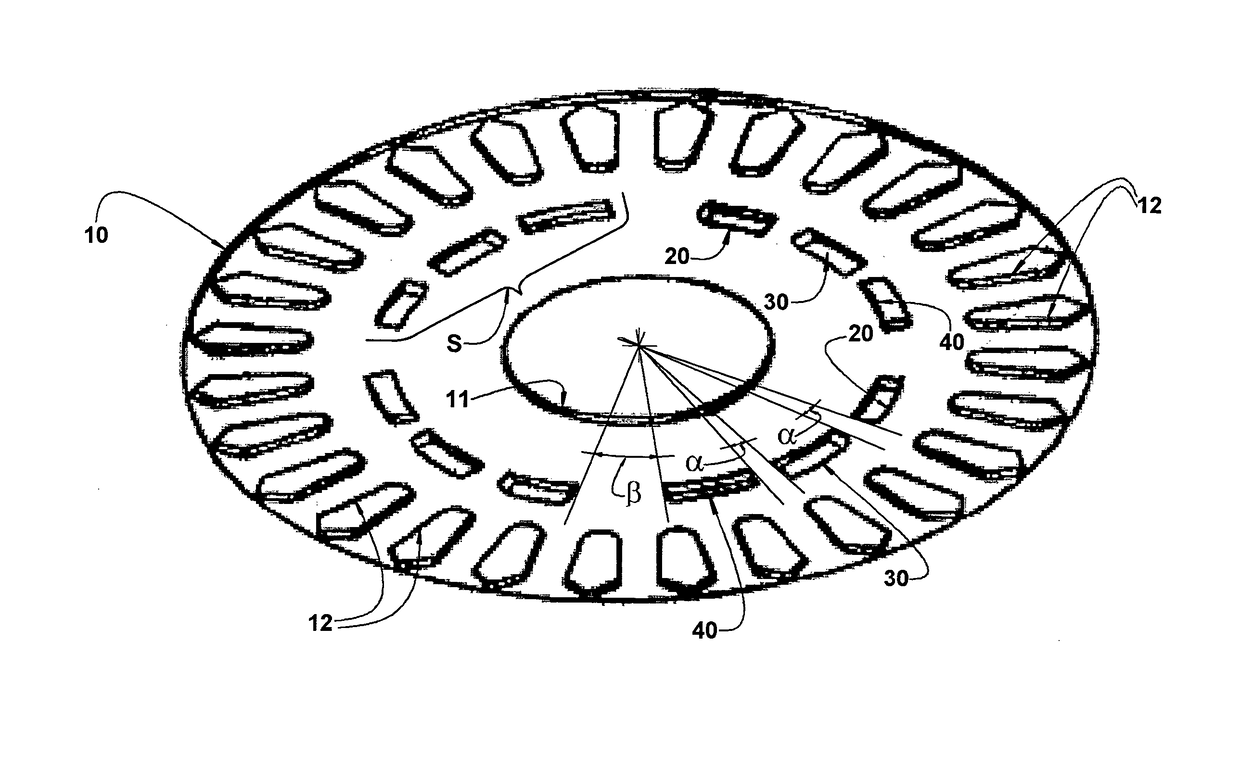
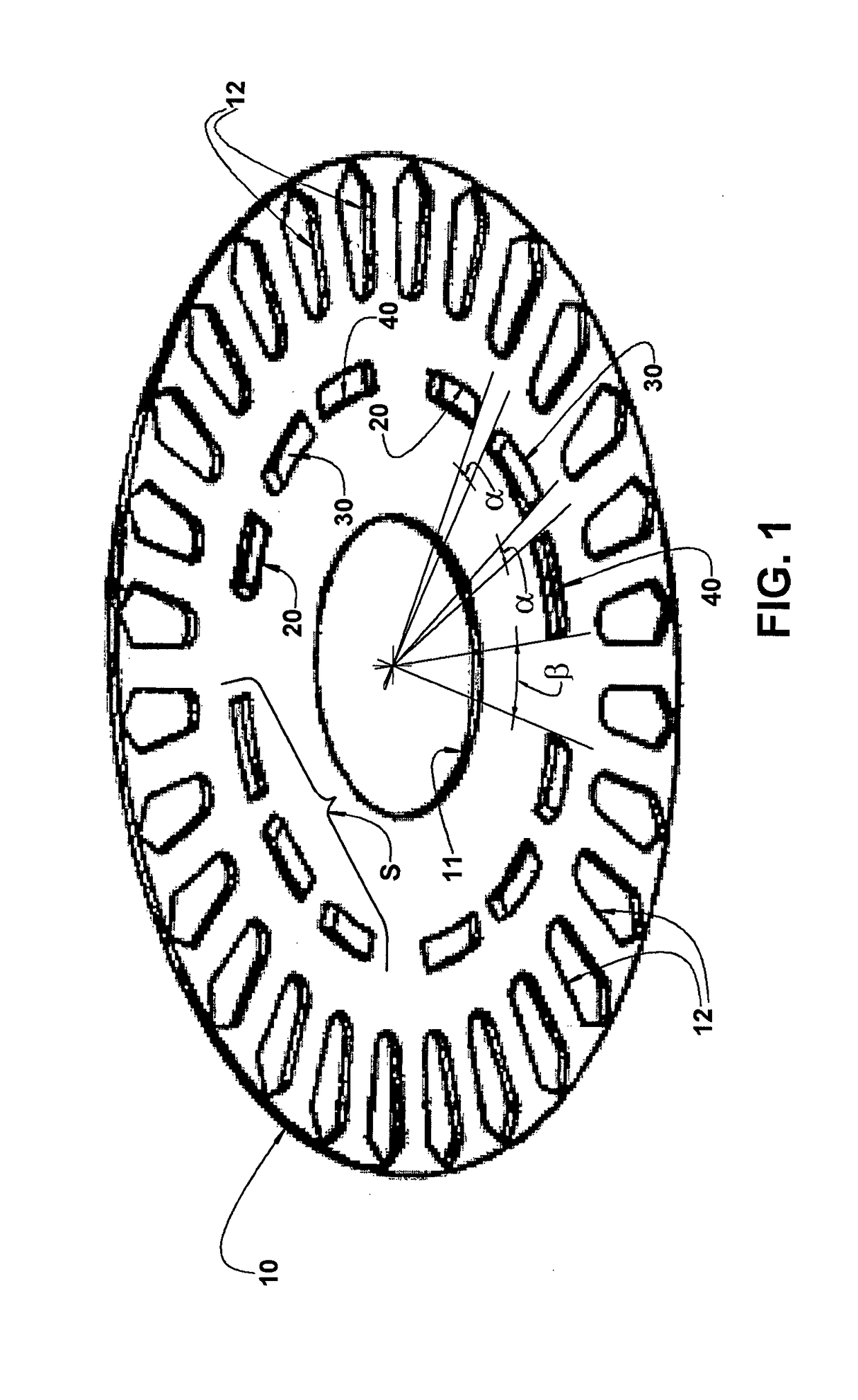
[0026]While the description below is related to metallic laminations 10 in the form of circular discs, to be applied in the formation of a lamination stack, for example of an electric motor, it should be understood that the invention can be applied to fasten two or more laminations to each other, for different applications.

[0027]As illustrated in the drawings, the laminations 10 present a central hole 11 which is usually obtained by stamping a metallic plate 1 in a stamping unit 2 provided with a stamping punch 3 and with a support matrix 4 for the already formed laminations 10 and in which the laminations 10 are progressively stacked and locked to each other.

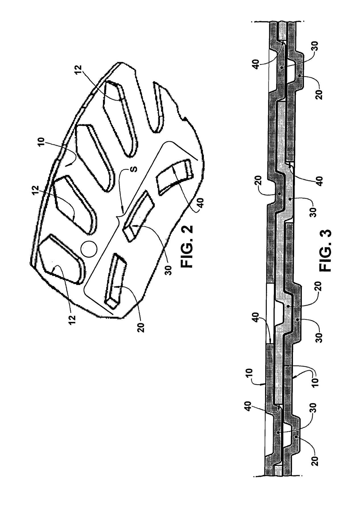
[0028]The lamination stack of the present invention comprises a plurality of superposed metallic laminations 10, each lamination 10 comprising at least one assembly S of coupling elements, said assembly S comprising one insertion clamp 20, one receiving clamp 30 and at least one receiving window 40.

[0029]The insertion clamp 20 ...


PUM

PropertyMeasurementUnit
metallicaaaaaaaaaa
displacementaaaaaaaaaa
shapeaaaaaaaaaa

Abstract

Each lamination of the lamination stack comprises at least one assembly of coupling elements, said assembly comprising one insertion clamp, one receiving clamp and at least one receiving window, said coupling elements maintaining the same relative positioning from one another, the insertion clamp and the receiving clamp being defined by respective portions of the lamination axially projecting to the same side of the latter, each insertion clamp of a lamination being fitted, by interference, in the interior of a receiving clamp of an adjacent lamination, and each receiving clamp of a lamination being housed in the receiving window of at least one lamination of the stack.

Description

FIELD OF THE INVENTION[0001]The present invention refers, in general terms, to a lamination stack, for example of the type used in a stator and / or rotor of electric motors, such as those used in refrigeration compressors. The invention further refers to a process for carrying out the assembly and mutual fixation of metallic laminations upon stacking a plurality of said metallic laminations to form the stack.PRIOR ART[0002]There are known from the prior art some solutions for fastening metallic laminations together to form the lamination stack of an electric motor.[0003]In one of said known solutions, the metallic laminations that form the lamination stack are superposed and maintained in this position, by fitting, by interference, an insertion clamp (projection) produced in a lamination, into a receiving window (cavity) formed in an adjacent lamination, as disclosed in document EP0847109.[0004]In this solution, a progressive tool cuts a plate, which will form the lamination, in seve...

Claims


Application Information

Patent Timeline
Patent Type & Authority Patents(United States)
IPC IPC(8): H01F3/04H02K1/06H02K1/26H01F7/06H02K15/02
CPCH02K1/265H02K1/06H02K15/02H02K15/024H02K2201/09Y10T29/49009Y10T428/24322
Inventor WOLF, ANDERSONMERINI, ANDRE LUCASKNUPFER, HERMANN OTTOROSARIO, SERGIO DOGROTT, TARCISIO JOAO
Owner EMBRACO IND DE COMPRESSORES E SOLUCOES EM REFRIGERACAO LTDA
Why Eureka
Try Eureka