High frequency AC LED lighting system

a led lighting and high frequency technology, applied in lighting apparatus, electroluminescent light sources, light sources, etc., can solve problems such as remaining problems, and achieve the effect of increasing the amount of light emitted

Inactive Publication Date: 2017-09-26
ONCE
View PDF3 Cites 2 Cited by
  • Summary
  • Abstract
  • Description
  • Claims
  • Application Information

AI Technical Summary

Benefits of technology

[0007]A circuit having a series interconnection of a light-emitting diode (LED) group, a first transistor, a second transistor and a first resistor. The series interconnection has a cathode coupled to a drain terminal of the first transistor and a source terminal of the first transistor is coupled to a first terminal of the first resistor wherein voltage across the first resistor provides a biasing voltage for the first transistor. A source terminal of the second transistor is coupled to a first terminal of the first resistor wherein voltage across the second resistor provides a biasing voltage for the second transistor. Ancillary circuitry bypasses the series interconnection and has a capacitor to provide current to the series interconnection to increase the amount of light emitted during an electrical excitation cycle.

Problems solved by technology

While effective at operating and dimming, problems remain.

Method used


Image

  • High frequency AC LED lighting system
  • High frequency AC LED lighting system
  • High frequency AC LED lighting system

Examples


Embodiment Construction

[0020]In the following detailed description, numerous specific details are set forth by way of examples in order to provide a thorough understanding of the relevant teachings. However, it should be apparent to those skilled in the art that the present teachings may be practiced without such details. In other instances, well known methods, procedures, components, and / or circuitry have been described at a relatively high-level, without detail, in order to avoid unnecessarily obscuring aspects of the present teachings.

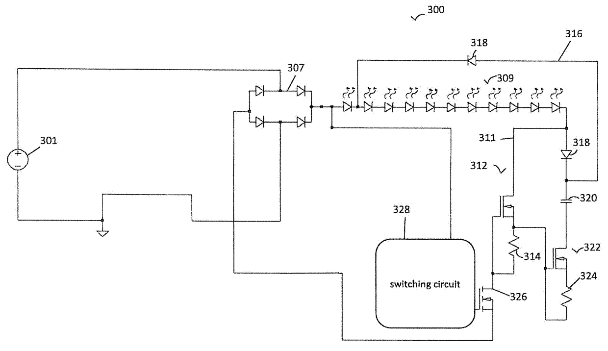
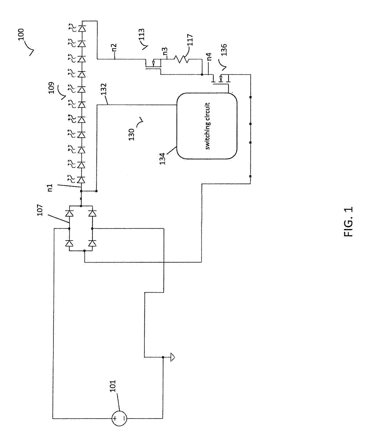
[0021]Driving circuitry for powering light emitting diode (LED) lights generally rely on digital circuitry to measure the instantaneous value of a driving voltage, on a microprocessor to identify LEDs to activate based on the measured value, and on digital switches to selectively activate the identified LEDs. The digital circuitry, however, reduces the overall efficiency of the LED lighting by causing harmonic distortion and power factor distortion in the LED light and th...


PUM


Abstract

A circuit having a series interconnection of a light-emitting diode (LED) group, a first transistor, a second transistor and a first resistor. The series interconnection has a cathode coupled to a drain terminal of the first transistor and a source terminal of the first transistor is coupled to a first terminal of the first resistor wherein voltage across the first resistor to provide a biasing voltage for the first transistor. A source terminal of the second transistor is coupled to a first terminal of the first resistor wherein voltage across the second resistor provides a biasing voltage for the second transistor and ancillary circuitry bypasses the series interconnection. The ancillary circuitry has a capacitor to provide current to the series interconnection to increase the amount of light emitted during an electrical excitation cycle.

Description

CROSS REFERENCE[0001]This application is based upon and claims benefit to U.S. Provisional Patent Application Ser. No. 62 / 261,589 filed Dec. 1, 2015 entitled High Frequency AC LED Lighting System to Grajcar et al. and that application is incorporated by reference in full.BACKGROUND[0002]This invention relates to LED lighting circuits. More specifically this invention relates to a circuit for providing improved operation of an LED lighting device.[0003]LED lighting is an energy efficient lighting source is becoming more and more popular world-wide. Several ways exist regarding how to successfully operate and dim LED devices. In particular, typically line voltage is AC or alternating current voltage where the voltage and current are represented by a sine wave. One circuit that can be used to operate and dim LED utilizes a rectifier and AC to DC converter in association with a PWM device to provide diming.[0004]In an alternative embodiment applicant eliminated the AC to DC converter an...

Claims


Application Information

Patent Timeline
Patent Type & Authority Patents(United States)
IPC IPC(8): H05B37/02H05B33/08H05B44/00
CPCH05B33/0845H05B33/0818H05B33/0833H05B33/0842H05B45/31H05B45/36H05B45/10H05B45/3725H05B45/355
Inventor GRAJCAR, ZDENKOHASKVITZ, DAVID
Owner ONCE
Why Eureka
Try Eureka