Umbrella device

a technology of umbrellas and straps, applied in the field of umbrellas, can solve the problems of inability to perform necessary tasks, inconvenient use, and injury to individuals, and achieve the effects of improving the comfort and convenience of us

Inactive Publication Date: 2017-10-03
HARRIS JANICE
View PDF21 Cites 4 Cited by
  • Summary
  • Abstract
  • Description
  • Claims
  • Application Information

AI Technical Summary

Benefits of technology

[0008]It is therefore an object of the present invention to provide a new and improved umbrella device that has all of the advantages of the prior art and none of the disadvantages. The umbrella includes a shaft having a handle on a first end and a canopy on an opposing second end. One or more ribs are secured to the canopy in order to support the canopy in an open configuration to prevent rain, sun, debris or other elements from contacting a user. Each rib includes one or more weights in order to stabilize the canopy. One or more magnets are secured to a lower end of each rib in order to removably secure the umbrella to a magnetic surface for hands-free use. An upper end of each rib is hingedly secured to the shaft. The ribs are operably connected to an actuatable button in the handle so as to extend the ribs outward from the shaft in order to expand the canopy into the open configuration.

Problems solved by technology

However, it is difficult to perform necessary tasks, such as buckling and unbuckling children and loading and unloading groceries and other items from a vehicle, with the use of only one hand.
As a solution, some people attempt to balance the umbrella between an open vehicle door and the vehicle roof, but this is not sturdy or reliable and the umbrella can easily fall and cause injury to the individual due to pointed ends of the umbrella.
However, these devices fail to provide an umbrella having a plurality of ribs that terminate with a magnetic fastener.
Further, these devices fail to provide ribs with weighted elements therein for adding stability to the umbrella during harsh weather conditions.

Method used


Image

  • Umbrella device
  • Umbrella device
  • Umbrella device

Examples


Embodiment Construction

[0014]Reference is made herein to the attached drawings. Like reference numerals are used throughout the drawings to depict like or similar elements of the umbrella device. For the purposes of presenting a brief and clear description of the present invention, the preferred embodiment will be discussed as used for removably securing an umbrella to a vehicle in order for use in a hands-free manner. The figures are intended for representative purposes only and should not be considered to be limiting in any respect.

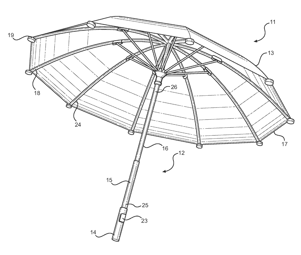
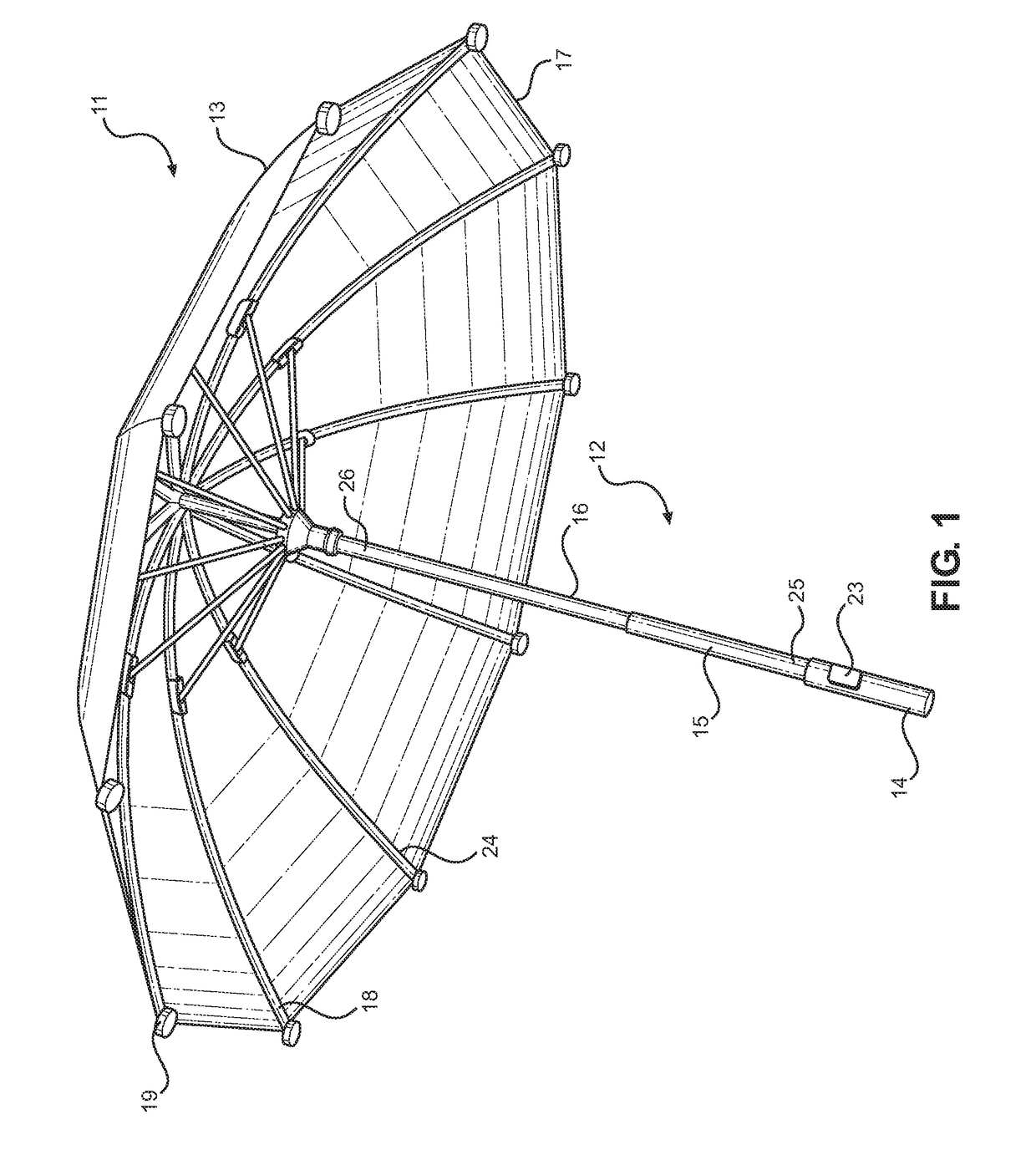
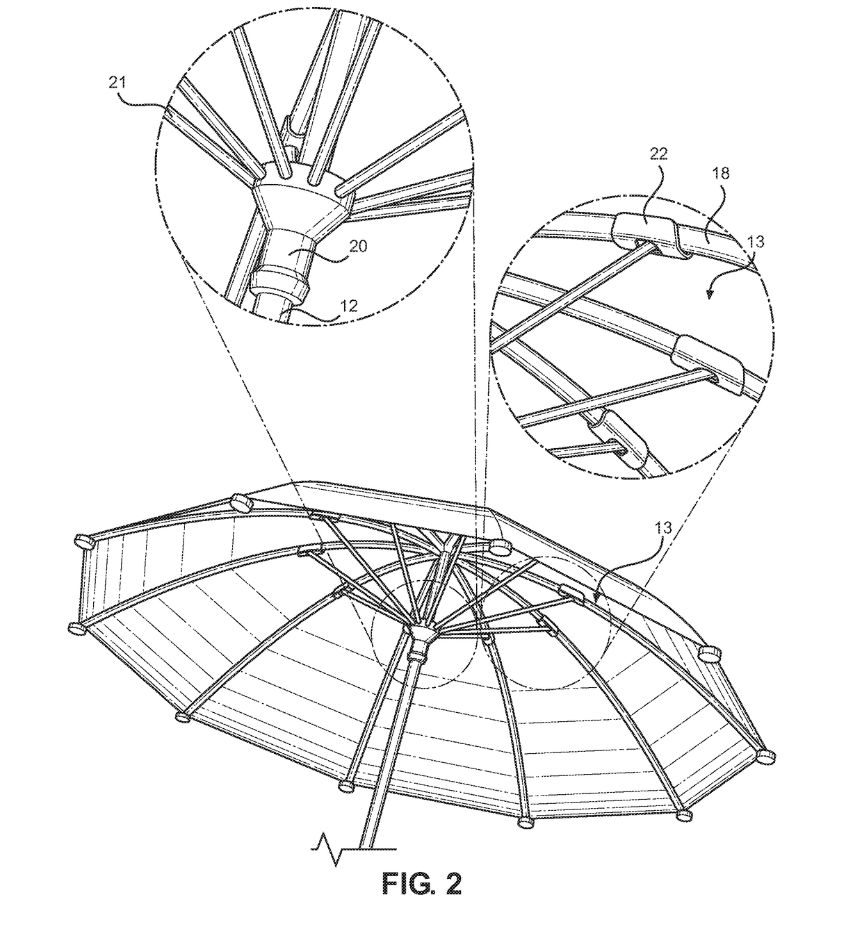
[0015]Referring now to FIGS. 1 and 2, there is shown a perspective view of an embodiment of the umbrella device and a close-up view of the upper end of the umbrella device, respectively. The umbrella device 11 includes a shaft 12 having a first end and an opposing second end, wherein the first end includes a handle 14 for allowing a user to grasp the umbrella device 11. The second end includes a canopy 13 adapted to shield a user disposed therebeneath from rain, sun, and the ...


PUM


Abstract

An umbrella for removably securing to a surface, such as a vehicle. The umbrella includes a shaft having a handle on a first end and a canopy on an opposing second end. One or more ribs are secured to the canopy in order to support the canopy in an open configuration. Each rib includes one or more weights in order to stabilize the canopy when secured to a surface. One or more magnets are secured to a lower end of each rib in order to removably secure the umbrella to a magnetic surface for hands-free use. An upper end of each rib is hingedly secured to the shaft. The ribs are operably connected to an actuatable button in the handle so as to extend the ribs outward from the shaft in order to expand the canopy into the open configuration.

Description

CROSS REFERENCE TO RELATED APPLICATION[0001]This application claims the benefit of U.S. Provisional Application No. 62 / 241,224 filed on Oct. 14, 2015. The above identified patent application is herein incorporated by reference in its entirety to provide continuity of disclosure.BACKGROUND OF THE INVENTION[0002]The present invention relates to umbrellas. More specifically, the present invention provides an umbrella that removably secures to a magnetic surface, such as a roof of a vehicle.[0003]When it rains many people use umbrellas in order to shield themselves from becoming soaked when traveling to and from their vehicle. In order to use an umbrella, an individual must hold the umbrella with at least one hand. However, it is difficult to perform necessary tasks, such as buckling and unbuckling children and loading and unloading groceries and other items from a vehicle, with the use of only one hand.[0004]As a solution, some people attempt to balance the umbrella between an open veh...

Claims


Application Information

Patent Timeline
Patent Type & Authority Patents(United States)
IPC IPC(8): A45B11/00A45B25/24A45B25/08A45B19/04A45B25/02A45B25/16
CPCA45B11/00A45B19/04A45B25/02A45B25/08A45B25/16A45B25/24
Inventor HARRIS, JANICE
Owner HARRIS JANICE
Why Eureka
Try Eureka