Fastener stringer

a technology of fastener and stringer, which is applied in the field of fastener stringers, can solve the problems of increasing the instability of the engagement of the stop claw portion in the slider of the fastener stringer in patent document 1 with the fastener element, etc., and achieves the effect of reducing the cost of molding dies, reducing the manufacturing cost of the slide fastener and ensuring the appearan

Active Publication Date: 2017-10-17
YKK CORP
View PDF13 Cites 0 Cited by
  • Summary
  • Abstract
  • Description
  • Claims
  • Application Information

AI Technical Summary

Benefits of technology

[0044]In the fastener stringer according to the invention, each of the fastener elements made of synthetic resin is fixed so as to extend across the first tape surface and the second tape surface of the fastener tape, and includes the element main body portion having the body portion, the neck portion and the coupling head portion and the first and the second projections which project from the first surface and the second surface of the element main body portion.
[0045]Further, the outer surface of the first projection and the outer surface of the second projection in the fastener element include at least one top surface, the peripheral side surface which rises from the element main body portion, and at least one sloped surface which is between the top surface and the peripheral side surface and has a different inclination angle with respect to the top surface and the peripheral side surface. Here, the sloped surface means a surface of a region portioned with other surfaces such as a top surface and a peripheral side surface via a ridge line portion, and includes a curved surface which curves in a concave shape and a curved surface which curves in a convex shape as well as a flat surface.
[0046]In the present invention, since the outer surface of the first projection and the outer surface of the second projection in the fastener element are formed of a plurality of the surfaces as described above, when the fastener element is viewed from the upper surface side or the lower surface side, the first and the second projections can be appeared thinner in the element length direction with respect to the fixing region of the element main body portion fixed to the first tape surface and the second tape surface. As another effect, it becomes possible to reflect light with each of the surfaces of the fastener element, so that it is possible to provide the fastener element with a gloss like a metal. Therefore, the fastener element made of synthetic resin in the present invention can exhibit a closer appearance (show) to the metallic fastener element.
[0047]Further, in the fastener stringer according to the present invention, since each of the fastener elements has a tapered shape on the front and back surfaces of the element main body portion as described above, or the first and the second projections having a gloss like a metal, it becomes possible to be used for a so-called slide fastener with right-side insertion and also with left-side insertion. Therefore, it is possible to reduce the cost for molding dies for element and to obtain a manufacturing cost reduction of the slide fastener.
[0048]In such a fastener stringer according to the present invention, the first projection of the fastener element includes the element base disposed on the body portion and the element tip end portion extending from the element base toward the coupling head portion side in the tape width direction and has the tapered shape in which the dimension in the tape length direction gradually decreases toward the tip end. Further, the element tip end portion of the first projection has the intermediate sloped surface which slopes upward from the peripheral side surface to the top portion including the top surface so as to have a smaller inclination angle with respect to the first tape surface of the fastener tape than that of the peripheral side surface.
[0049]Accordingly, it is possible to provide a fastener element which can be appeared thinner in the element length direction than the actual element fixing region with respect to the fastener tape as described above. Further, it is possible to provide the outer surface of the first projection with a gloss like a metal as described above. In addition, for example, in a case that a slide fastener is formed using a slider with a stopping mechanism in which a stop claw portion is disposed so as to correspond to an element tip end portion of a fastener element, it is possible to receive the stop claw portion of the slider on the peripheral side surface of the first projection in the fastener element and to secure the engagement of the stop claw portion with respect to the fastener element.

Problems solved by technology

However, for example, in a case that a slide fastener is formed using fastener stringers according to Patent Document 1 and a slider with a stopping mechanism having a stop claw portion which is capable of being engaged to a fastener element, the engagement of the stop claw portion in the slider of the fastener stringer in Patent Document 1 with the fastener element can be easily unstable since a convex surface is formed on the first half portion of the fastener element.
This is one of the factors causing manufacturing cost increase of the slide fastener.

Method used


Image

  • Fastener stringer
  • Fastener stringer
  • Fastener stringer

Examples


first embodiment

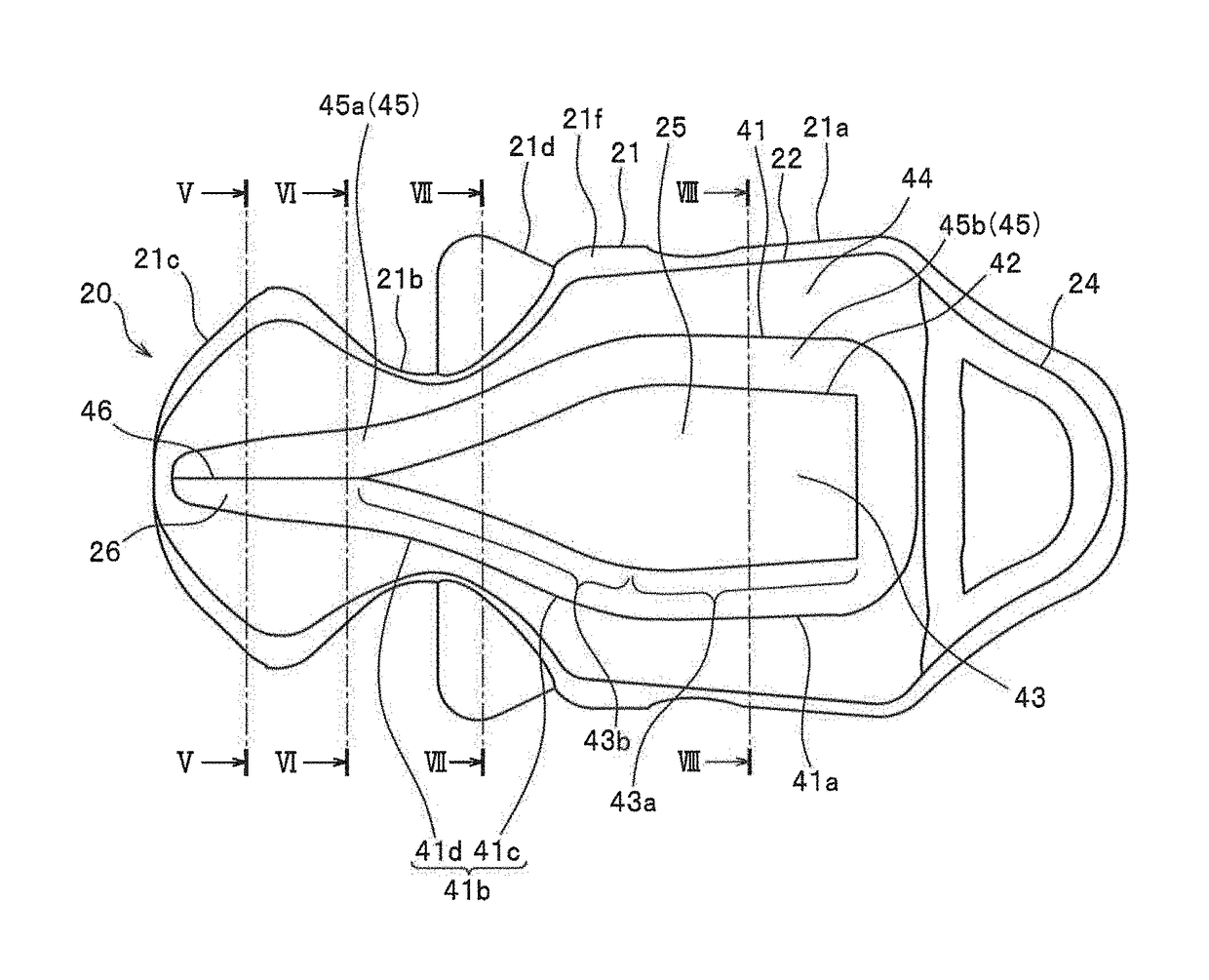
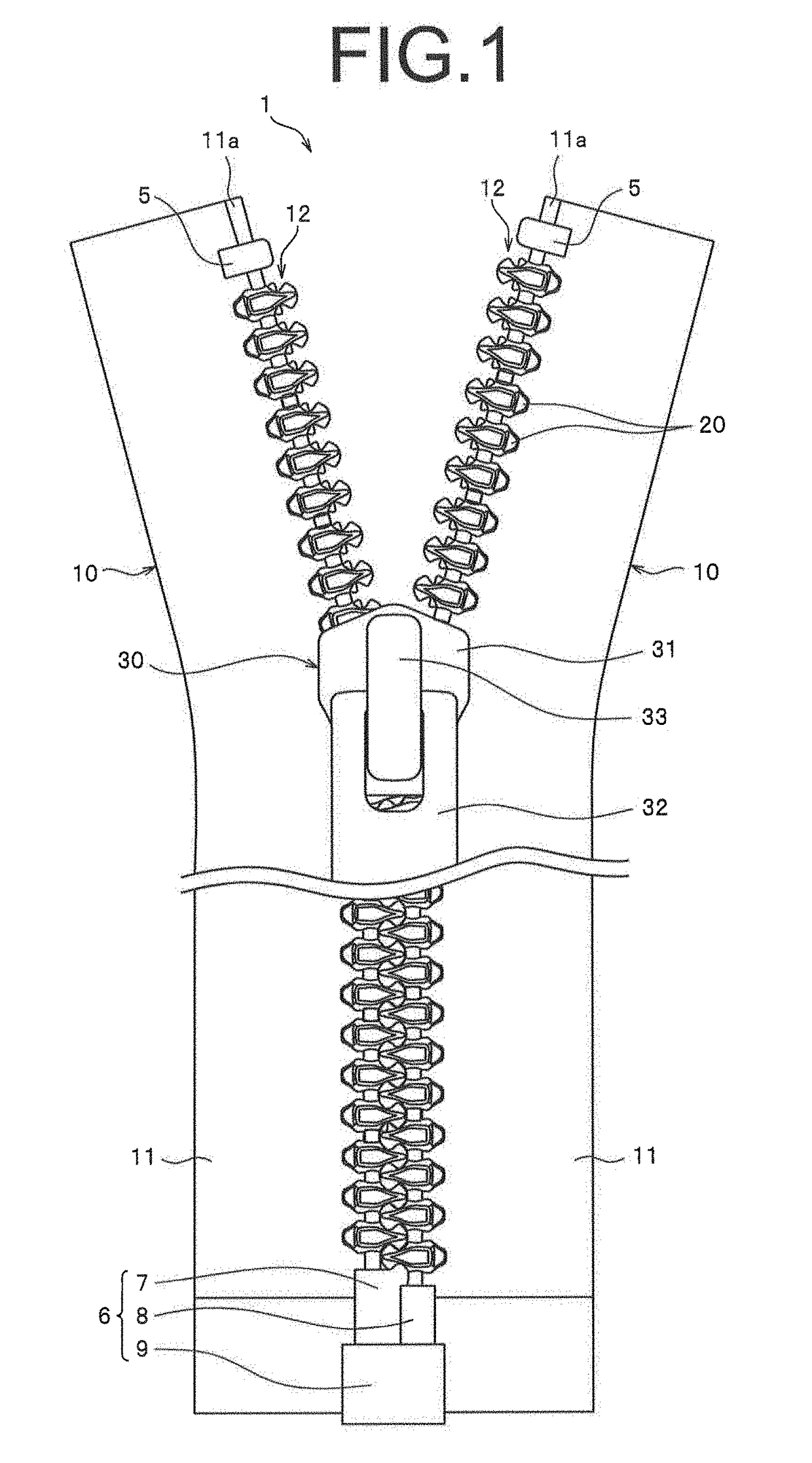
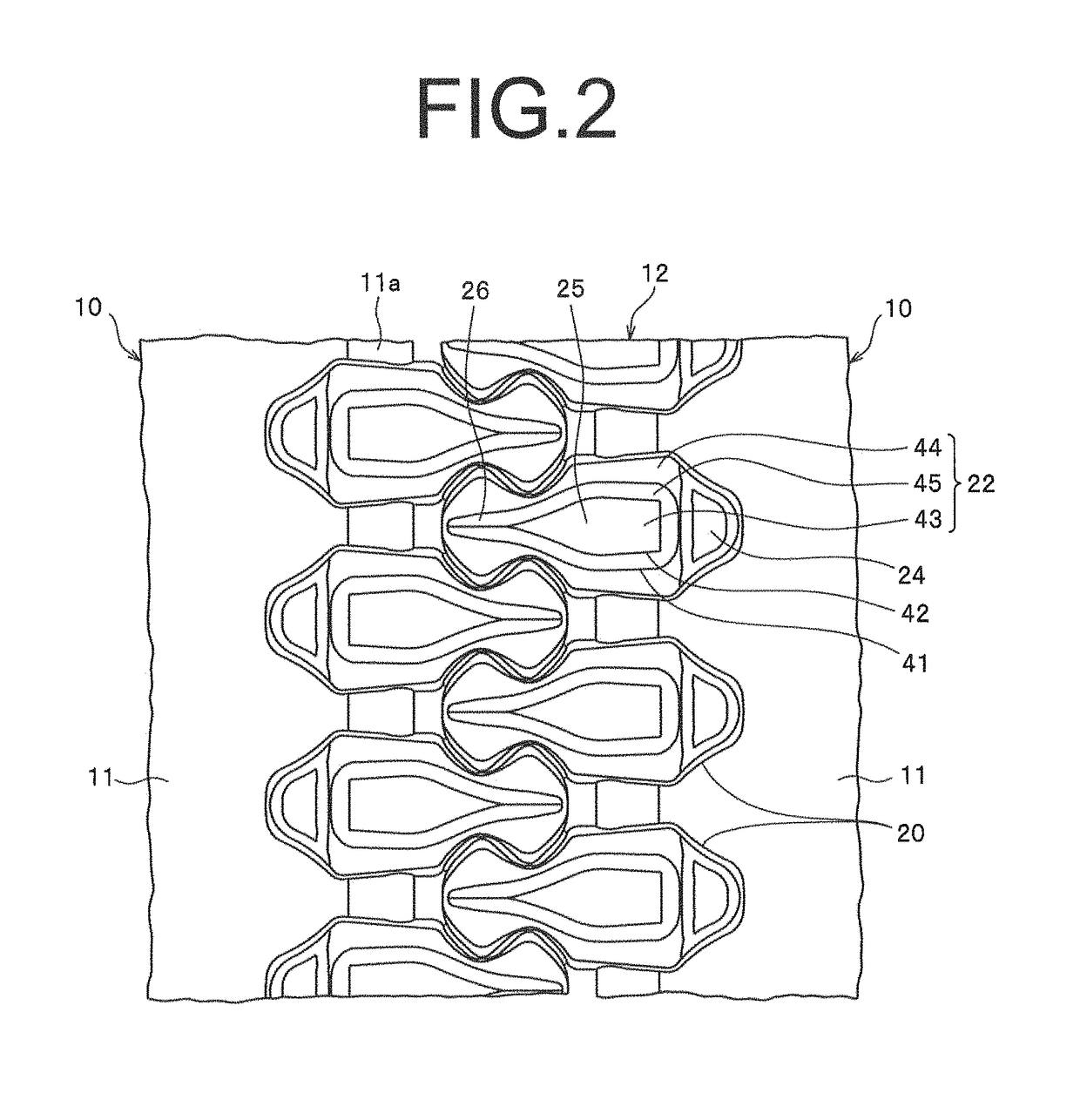
[0079]FIG. 1 is a plan view showing a slide fastener which has a fastener stringer according to a first embodiment of the invention. FIG. 2 is an enlarged plan view showing an enlarged main parts of the slide fastener. FIG. 3 and FIG. 4 are a plan view and a front view of a fastener element of the slide fastener. FIG. 5-FIG. 8 are sectional views shown in FIG. 3.

[0080]Further, in the description below, a tape length direction of the fastener tape is defined as a top and bottom direction. In particular, a direction in which the slider is slid when closing the slide fastener is defined as a top, and a direction in which the slider is slid when opening the slide fastener is defined as a bottom. Further, a tape width direction of the fastener tape is defined as a left and right direction. In addition, a tape front and back direction of the fastener tape is defined as an upper and lower direction, and a side where a pull tab of the slider is disposed with respect to the fastener tape is ...


PUM


Abstract

These fastener elements have: an element main body portion having a coupling head portion; and first and second projections that project in a tape surface / rear-surface direction from the element main body portion. The first and second projections have a top surface, peripheral side surfaces standing upright from the element main body portion, and at least one sloped surface between the top surface and the peripheral side surfaces that has a different angle of inclination from the top surface and the peripheral side surfaces. As a result, the fastener elements appear long and narrow in the element length direction and have an external appearance close to that of a metal element. Furthermore, a stop claw portion is less likely to catch on the fastener elements when starting the sliding operation of a slider.

Description

[0001]This application is a national stage application of PCT / JP2014 / 053651, which is incorporated herein by reference.TECHNICAL FIELD[0002]The invention relates to a fastener stringer in which a plurality of fastener elements made of synthetic resin are arranged by injection molding in a tape side edge portion of a fastener tape. In particular, the invention relates to a fastener stringer in which each fastener element made of synthetic resin has an appearance like a metallic fastener element.BACKGROUND ART[0003]As a fastener element which is conventionally used for a slide fastener, a fastener element made of synthetic resin which is formed individually by injection-molding synthetic resin onto a fastener tape, a continuous fastener element which is formed by molding a mono-filament in a coiled shape or a zigzag shape, and a metallic fastener element which is formed by caulking an approximately Y-shaped metallic element material onto a fastener tape, and the like are known.[0004]F...

Claims


Application Information

Patent Timeline
Patent Type & Authority Patents(United States)
IPC IPC(8): A44B19/06
CPCA44B19/06Y10T24/255Y10T24/2539
Inventor KOJIMA, MASAYOSHI
Owner YKK CORP
Why Eureka
Try Eureka