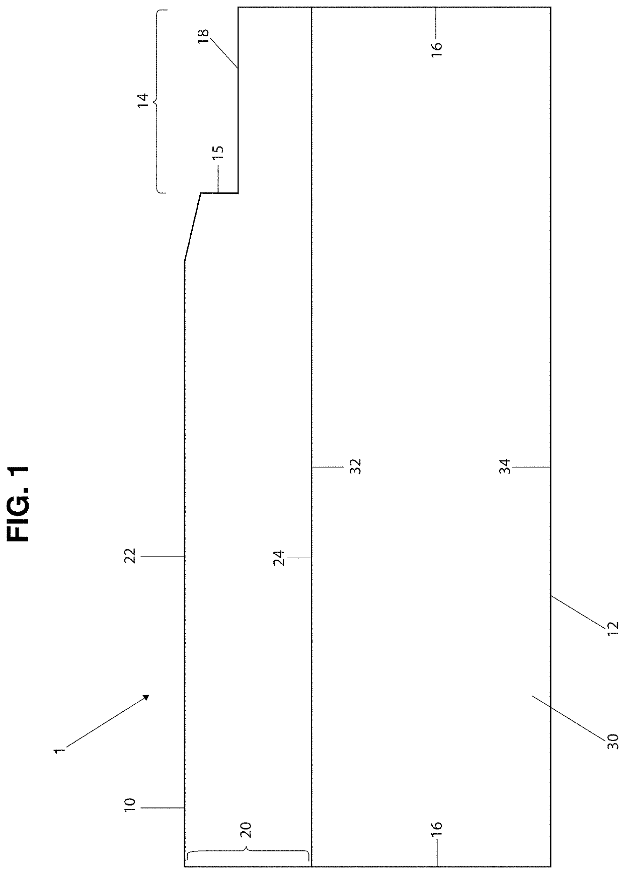
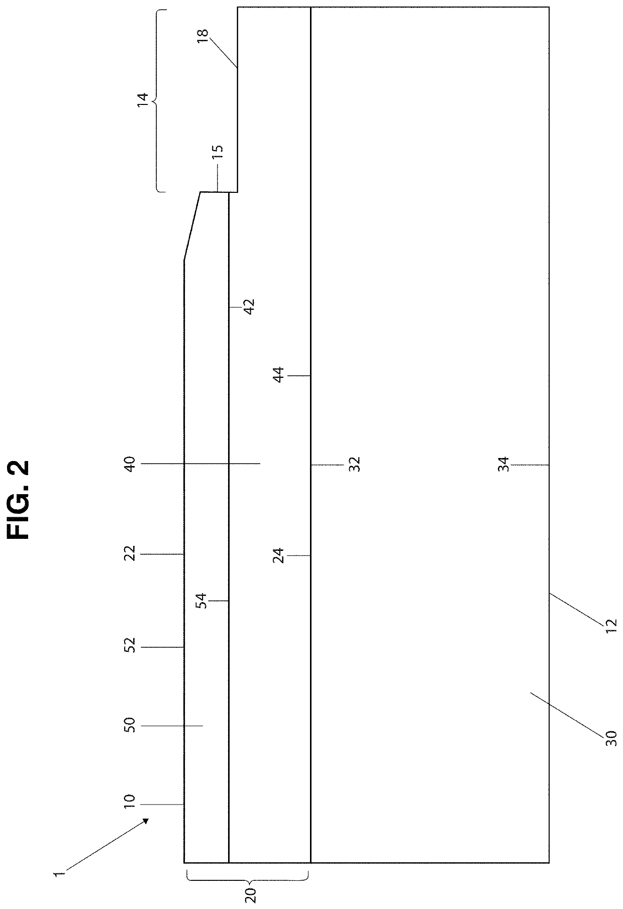
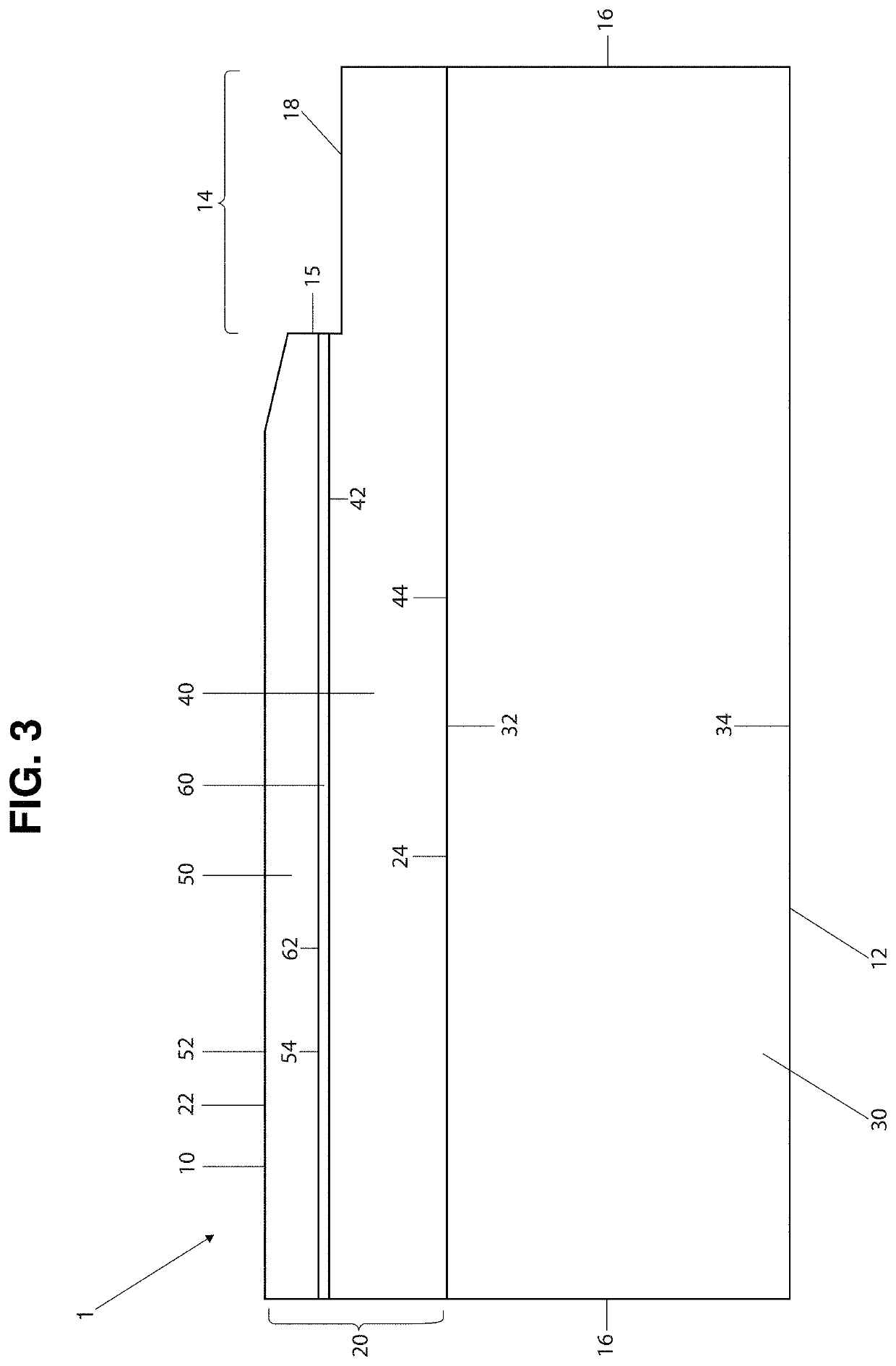
Tile with imitation grout line

Pending Publication Date: 2022-07-07
COUREY STEPHEN +1
View PDF0 Cites 1 Cited by
  • Summary
  • Abstract
  • Description
  • Claims
  • Application Information

AI Technical Summary

Problems solved by technology

Forming this separation between tiles is often tedious and requires the use of spacers to ensure uniformity and alignment of the tiles.
In general, the process of installing tile and creating the grout line involves a significant amount of time, which adds to the labor and overall cost of the project.
While this slight separation may be observable and in some cases may appear as a small seam or even as a micro groove, these types of known tiles do not offer any structure to represent or closely resemble the look and feel of a real grout line.
Furthermore, no such tiles or flooring products are believed to have ever featured a top layer of material, such as polyvinyl chloride (PVC), combined with a colorant during the manufacturing process so as to provide a variety of colors for the imitation grout line that will match with or closely correspo

Method used


Image

  • Tile with imitation grout line
  • Tile with imitation grout line
  • Tile with imitation grout line

Examples


Embodiment Construction

[0080]The present invention is directed towards a tile 1, such as a flooring tile, made from synthetic materials and so as to imitate the look and feel of real stone, marble, ceramic, wood or other materials, but which is further structured to offer a simulated grout line, with a highly realistic look and feel, on or along at least one side or edge of the tile 1. While the tile 1 of the present invention is particularly well suited for use as a flooring tile, it may also readily be used on wall surfaces or in a variety of other applications, and should not be considered as being limited only to flooring applications. As will also be described with regard to at least one embodiment, the tile 1 of the present invention may also be manufactured so as to include a very thin veneer layer of genuine wood or stone.

[0081]In general terms, the tile 1 of the present invention comprises an upper or top section, a lower or core section, and a plurality of sides. For example, and with reference ...


PUM

PropertyMeasurementUnit
Thicknessaaaaaaaaaa
Plasticityaaaaaaaaaa

Abstract

A tile for use as a covering on a floor, wall, or other surface comprising a top section disposed on a rigid core layer, wherein the top section comprises in some embodiments a veneer layer, or another layer or coating of material, such as polyurethane, upon which at least one design element may be imparted, such as through printing processes. The inventive tile in some embodiments described herein further comprises an exposed portion, or a plurality thereof, configured to provide a highly realistic imitation of a grout line. The inventive tile may also comprise at least one interconnecting mechanism, wherein such interconnecting mechanism may be formed on the same side of the tile as the exposed portion. In at least one embodiment, the layer or coating of material is disposed in covering relation to the exposed portion, and alternatively, a protective layer may instead be applied onto the exposed portion.

Description

CLAIM OF PRIORITY[0001]This application is a Continuation-in-Part of a currently pending patent application having Ser. No. 17 / 002,418, filed on Aug. 25, 2020 and set to issue as U.S. Pat. No. 11,149,442 on Oct. 19, 2021, which is a continuation of currently pending patent application having Ser. No. 16 / 358,241 and a filing date of Mar. 19, 2019, which itself is a Continuation in Part (CIP) of a patent application having Ser. No. 16 / 196,974 and a filing date of Nov. 20, 2018, which claims priority to a Continuation in Part (CIP) patent application having Ser. No. 15 / 950,046 and a filing date of Apr. 10, 2018 and which matured into U.S. Pat. No. 10,132,088 on Nov. 20, 2018, which in turn claimed priority to a patent application having Ser. No. 15 / 454,650 and a filing date of Mar. 9, 2017, which matured into U.S. Pat. No. 9,938,726 on Apr. 10, 2018, which in turn claimed priority to a U.S. provisional patent application having Ser. No. 62 / 380,122 and a filing date of Aug. 26, 2016. In...

Claims


Application Information

Patent Timeline
IPC IPC(8): E04F15/02E04F15/10B32B3/06B32B3/26B32B27/20B32B27/30
CPCE04F15/02033E04F15/02038E04F15/107B32B3/06B32B3/263B32B27/20B32B2307/72B32B2307/412E04F2201/0153E04F2201/023E04F2201/043B32B2419/04B32B2264/10B32B27/304E04F15/105B32B2255/26B32B2307/7265B32B2266/0235B32B2307/584B32B2255/102B32B2255/10B32B5/18B32B27/065B32B27/32B32B2264/104B32B27/08
Inventor COUREY, STEPHENALFIERI, MICHELE
Owner COUREY STEPHEN
Why Eureka
Try Eureka