
Support frame

a support frame and frame technology, applied in the field of support frames, can solve the problems of homeowners' various storage and maintenance problems, limited seating or table space, and unsightly and cluttered appearan

Inactive Publication Date: 2017-10-31
ROCKHILL JEFFREY A
View PDF40 Cites 5 Cited by
  • Summary
  • Abstract
  • Description
  • Claims
  • Application Information

AI Technical Summary

Benefits of technology

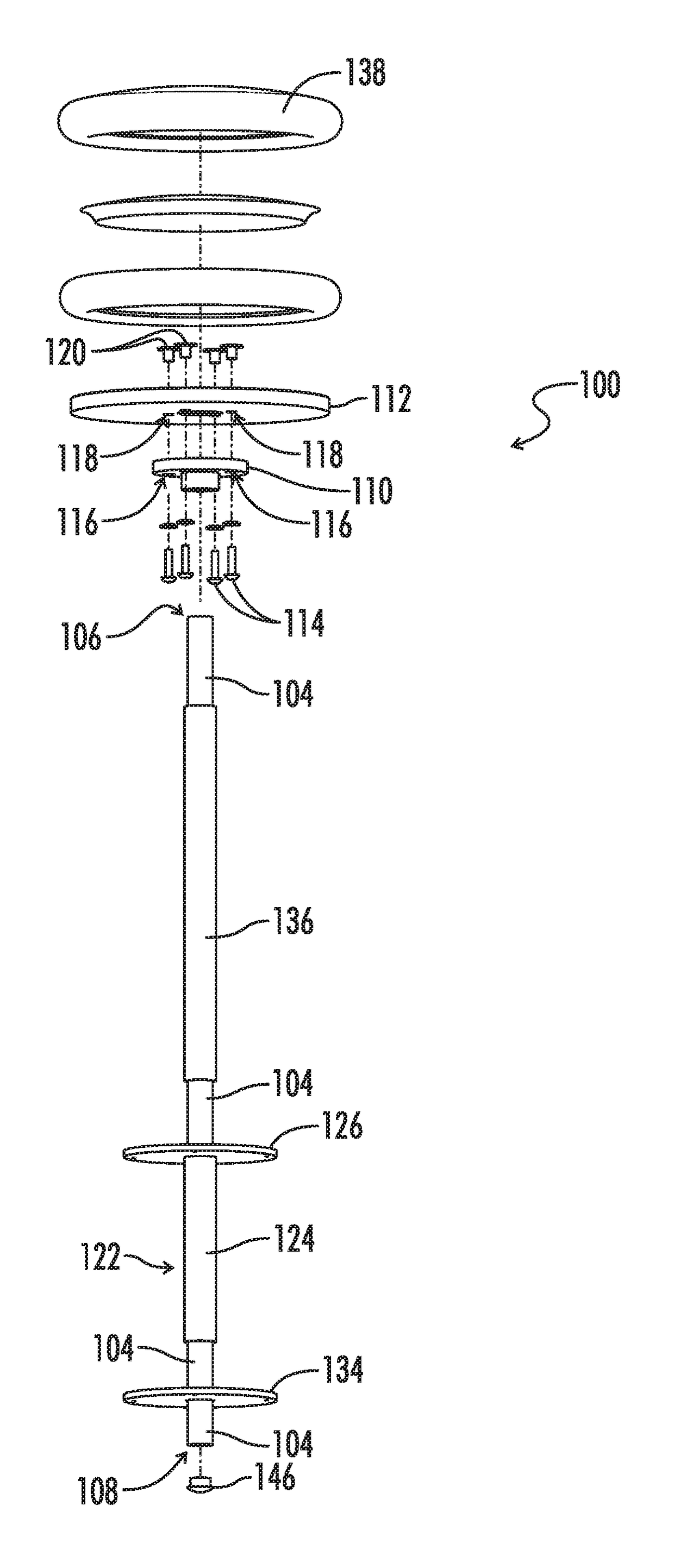
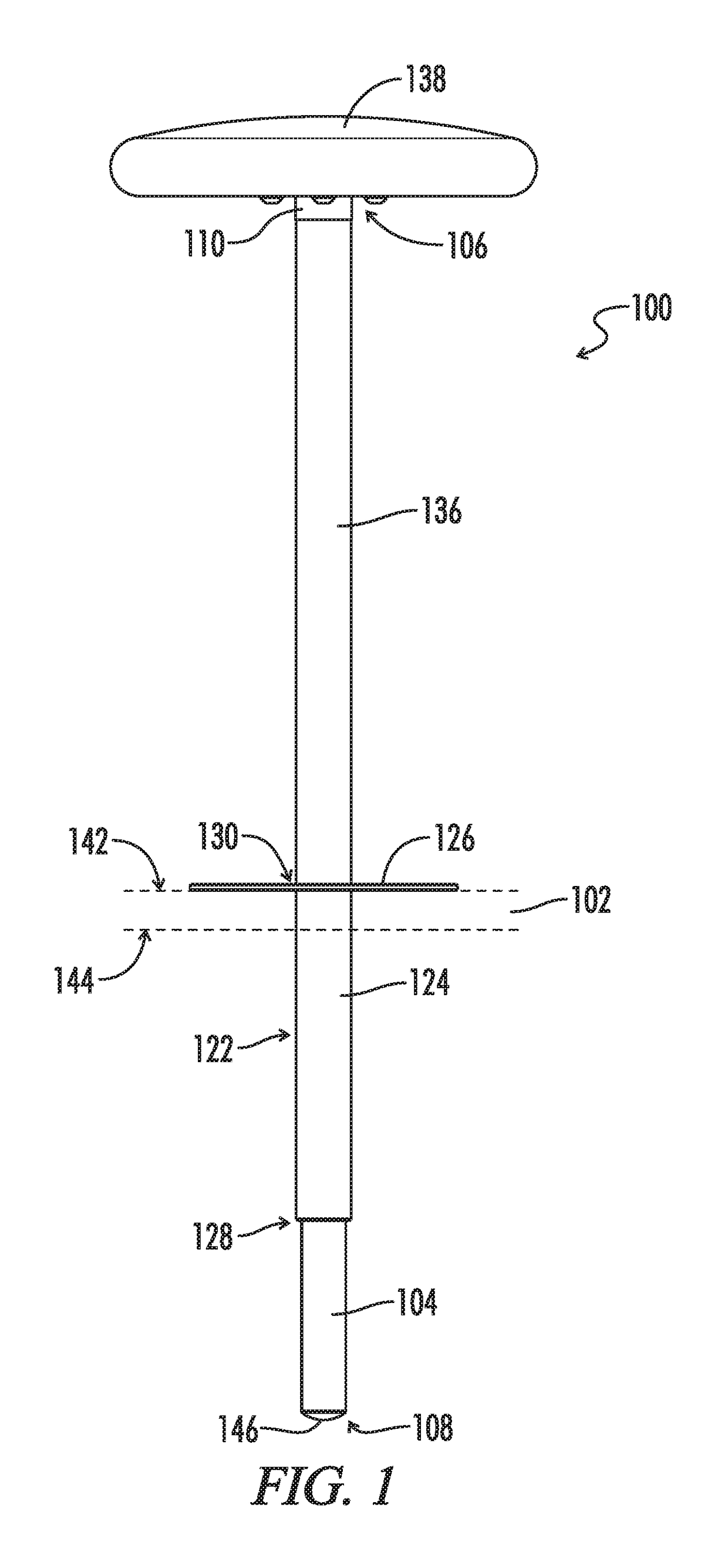
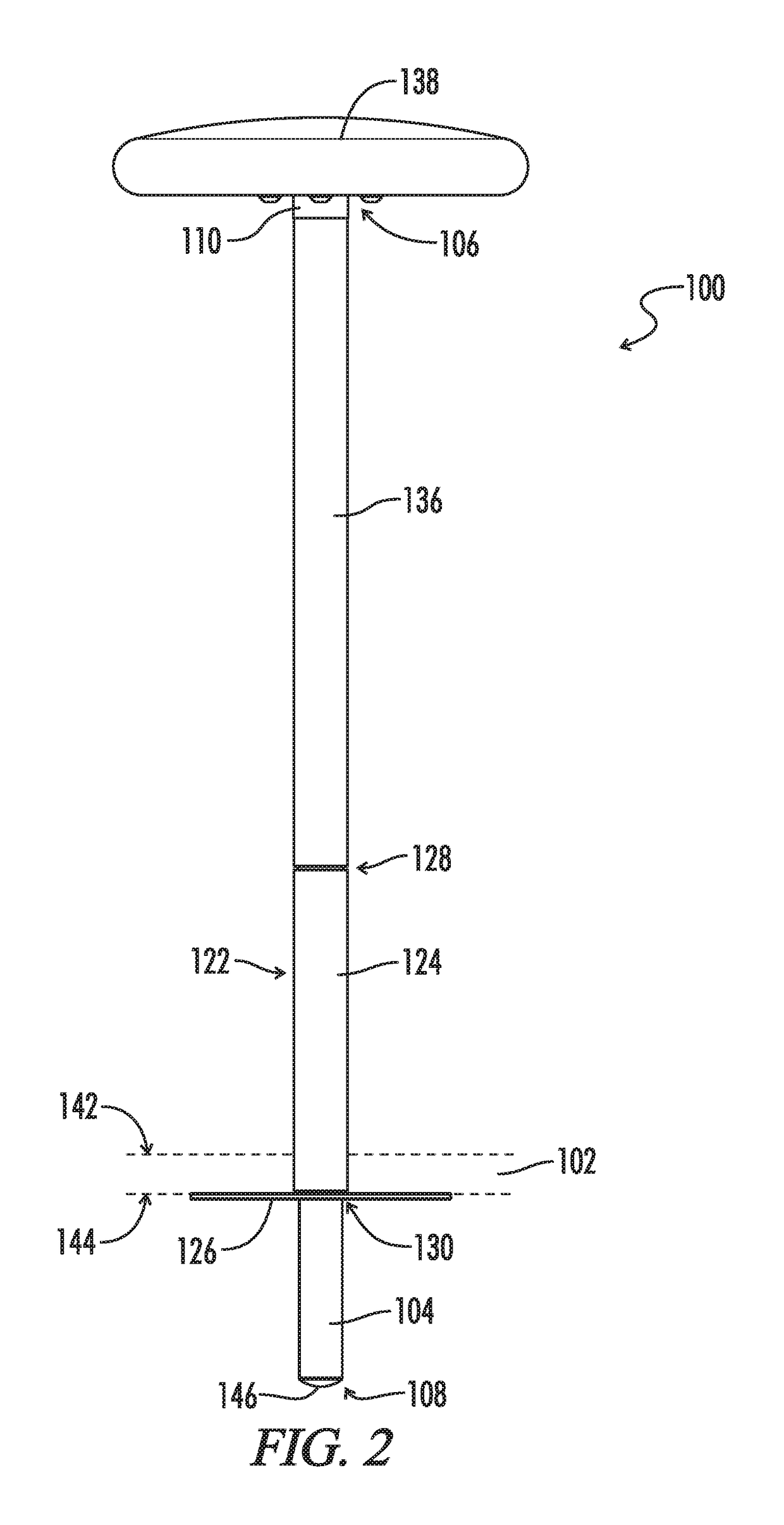
The present patent relates to a support frame for a support platform. The support frame includes an elongate rigid column, a platen bracket, a support platen, a flanged sleeve, a guide sleeve, and a backing plate. The flanged sleeve is connected to the elongate rigid column and includes a mounting flange that interfaces with the support platform. The guide sleeve is positioned between the flanged sleeve and the platen bracket and is designed to maintain the platen bracket and the flanged sleeve in a spaced apart orientation when the support frame is mounted on the support platform. The technical effects of the present patent include improved stability and secure mounting of the support frame on the support platform, as well as improved load bearing capacity.

Problems solved by technology

While a deck or patio may be a common gathering place for entertaining large groups of people, seating or table space is often limited.
Traditional patio furniture may be added, but such furniture can quickly create an unsightly and cluttered appearance.
Moreover, it presents various storage and maintenance problems for homeowners.
If the additional furniture is to be normally kept away from the deck, the homeowner must dedicate a great deal of space to storage.

Method used


Image

  • Support frame
  • Support frame
  • Support frame

Examples


Embodiment Construction

[0052]Reference will now be made in detail to embodiments of the present disclosure, one or more drawings of which are set forth herein. Each drawing is provided by way of explanation of the present disclosure and is not a limitation. In fact, it will be apparent to those skilled in the art that various modifications and variations can be made to the teachings of the present disclosure without departing from the scope of the disclosure. For instance, features illustrated or described as part of one embodiment can be used with another embodiment to yield a still further embodiment.

[0053]Thus, it is intended that the present disclosure covers such modifications and variations as come within the scope of the appended claims and their equivalents. Other objects, features, and aspects of the present disclosure are disclosed in, or are obvious from, the following detailed description. It is to be understood by one of ordinary skill in the art that the present discussion is a description o...


PUM


Abstract

A support frame may be mounted to a corresponding support platform. The support frame may include an elongate rigid column including a proximal end and a distal end opposite the proximal end. A platen bracket may be connected to the elongate rigid column nearer the proximal end than the distal end. A support platen may be connected to the platen bracket. A flanged sleeve may be coaxially received on the elongate rigid column nearer the distal end than the proximal end. The flanged sleeve may include a sleeve portion slidably received on the elongate rigid column and a mounting flange extending from the sleeve portion. The mounting flange may be configured to interface with the support platform. A guide sleeve may be coaxially received on the elongate rigid column between the platen bracket and the flanged sleeve. The guide sleeve may be configured to maintain the platen bracket and the flanged sleeve in a spaced apart orientation when the support frame is mounted to the corresponding support platform.

Description

CROSS-REFERENCES TO RELATED APPLICATIONS[0001]This application claims benefit of the following patent application which is hereby incorporated by reference:[0002]U.S. Provisional Application Ser. No. 62 / 164,680 entitled “Support Frame”, filed May 21, 2015.[0003]A portion of the disclosure of this patent document contains material that is subject to copyright protection. The copyright owner has no objection to the reproduction of the patent document or the patent disclosure, as it appears in the U.S. Patent and Trademark Office patent file or records, but otherwise reserves all copyright rights whatsoever.STATEMENT REGARDING FEDERALLY SPONSORED RESEARCH OR DEVELOPMENT[0004]Not ApplicableREFERENCE TO SEQUENCE LISTING OR COMPUTER PROGRAM LISTING APPENDIX[0005]Not ApplicableBACKGROUND[0006]The present disclosure relates generally to a support frame. More particularly, the present disclosure pertains to a support frame that may be disposed on or within a support platform including, but n...

Claims


Application Information

Patent Timeline
IPC IPC(8): A47C9/10F16M11/24A47B37/04A47C1/14A47C1/00A01K97/10F16M13/02A47C4/03
CPCF16M13/02A47B37/04A47C1/14F16M11/24A47C9/10A01K97/10A47C4/03A47B13/023A47B2220/0008A47C7/004A47C3/20A47C9/007
Inventor ROCKHILL, JEFFREY A.
Owner ROCKHILL JEFFREY A
Learn More