Fastener structure for pliers

a technology of fastener and pliers, which is applied in the field of fastener structure for pliers, can solve the problems of inconvenient operation of pliers and inconvenience of using them

Active Publication Date: 2017-11-07
WU LI TU
View PDF5 Cites 2 Cited by
  • Summary
  • Abstract
  • Description
  • Claims
  • Application Information

AI Technical Summary

Benefits of technology

[0006]The primary objective of the present invention is to provide a fastener structure for pliers which is configured between two handles of the pliers to fasten or unfasten the two handles safely.
[0010]Thereby, the fastening structure contains the slidable fastener to release or limit the first connecting arm and the second connecting arm so that the working segment is retracted safely. Furthermore, the slidable fastener is fixed on the gripping segment proximate to the connection portion of the two handles to correspond to the user's thumb, such that the slidable fastener is pushed easily by the user's thumb to release or limit the pliers.

Problems solved by technology

However, after retracting the pliers, the two handles are expanded opposite to a forcing direction of the fingers to cause using inconvenience.
Nevertheless, in operation, the retractable fastener is released or retracted by the user's other hand, thus operating the pliers inconveniently.

Method used


Image

  • Fastener structure for pliers
  • Fastener structure for pliers
  • Fastener structure for pliers

Examples


Embodiment Construction

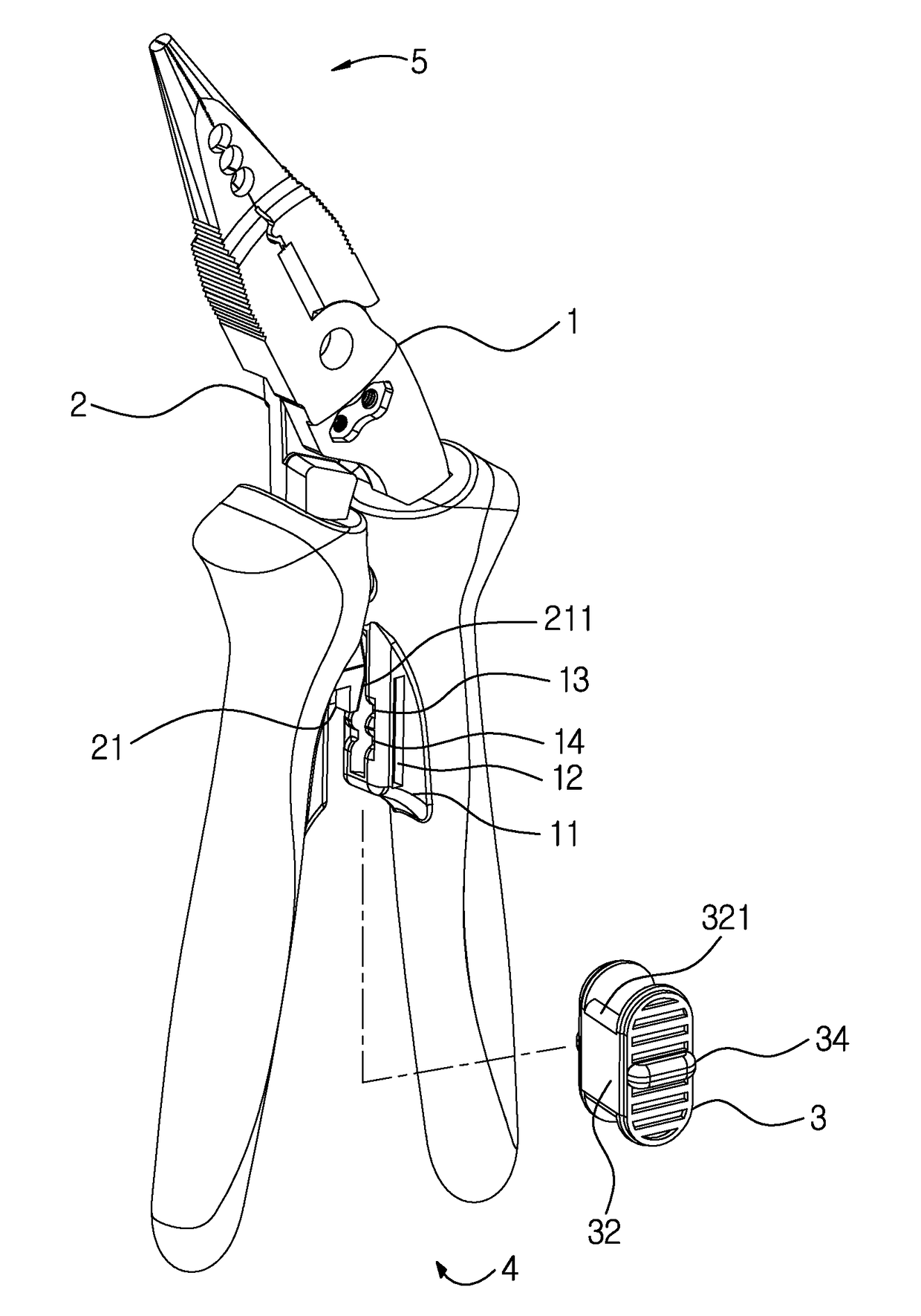
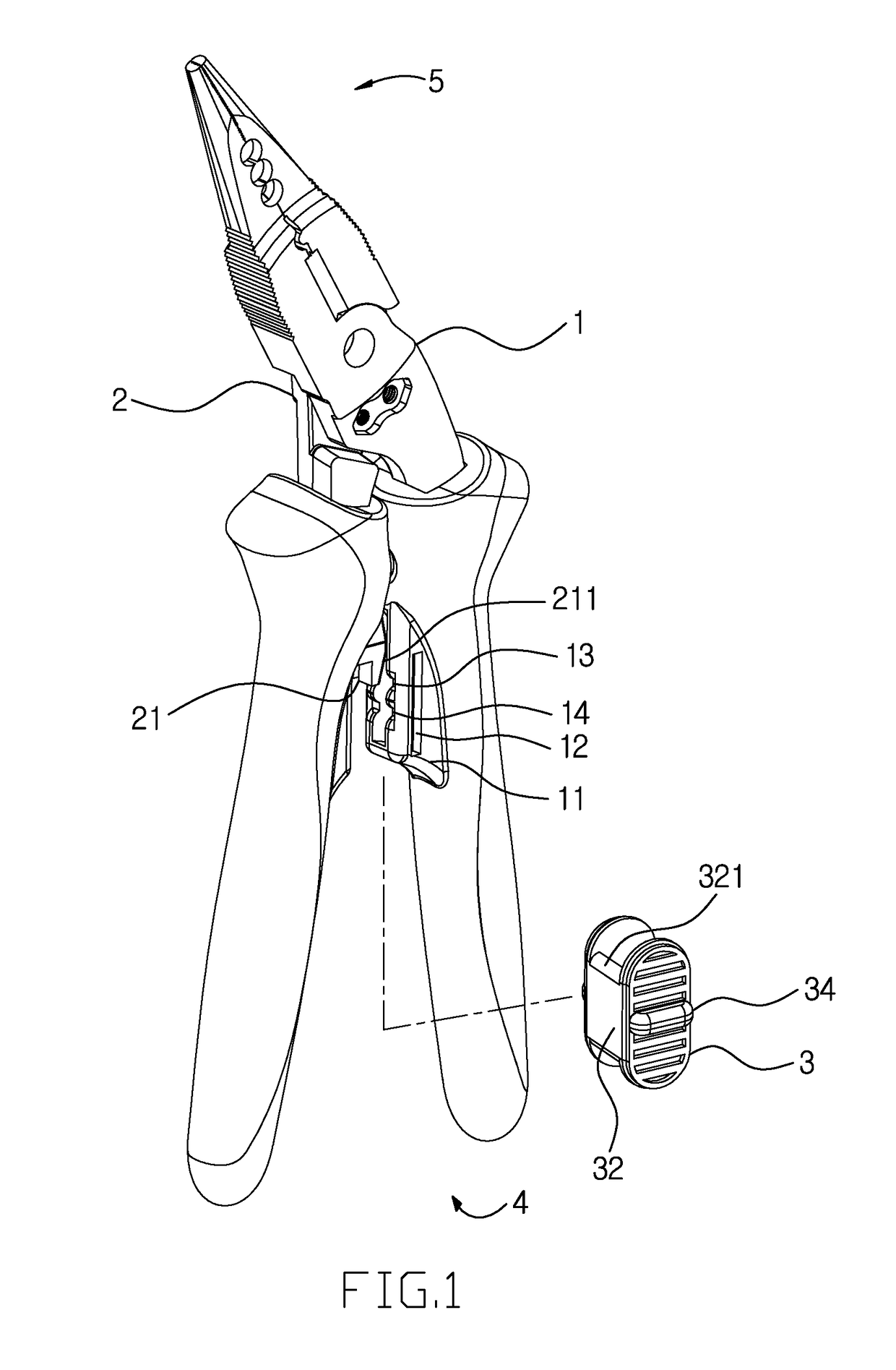
[0018]With reference to FIGS. 1-7, a fastener structure for pliers according to a preferred embodiment of the present invention is configured between two handles of the pliers to fasten or unfasten the two handles safely. The fastening structure comprises: a first connecting arm 1, a second connecting arm 2, and a slidable fastener 3.

[0019]The first connecting arm 1 is rotatably connected with the second connecting arm 2, such that a griping segment 4 and a working segment 5 are formed (In this embodiment, the working segment 5 is clamp pliers, and it can be also cutting pliers in another embodiment). The first connecting arm 1 includes a holder 11 disposed on a first inner wall of the griping segment 4, and the holder 11 has two guiding rails 12 fixed on two sides of the holder 11, a first notch 13 defined on an outer surface thereof, and a second notch 14 also defined on the outer surface thereof. The second connecting arm 2 includes a locking seat 21 secured on a second inner wal...


PUM


Abstract

A fastener structure for pliers contains: a first connecting arm, a second connecting arm, and a slidable fastener. The first connecting arm is rotatably connected with the second connecting arm to form a griping segment and a working segment and includes a holder which has two guiding rails. The first connecting arm also includes a first notch and a second notch, and the second connecting arm includes a locking seat. The slidable fastener is hollow and retains with the holder, and the slidable fastener includes two guide posts, a positioning plate, and an elastic locker mounted on the positioning plate to alternatively retain with the first notch or the second notch, such that when the elastic locker retains with the first notch, the positioning plate limits the locking seat, and when the elastic locker retains with the second notch, the positioning plate releases the locking seat.

Description

CROSS-REFERENCE TO RELATED APPLICATIONS[0001]This application is a continuation-in-part of U.S. application Ser. No. 14 / 188,691, filed on Feb. 25, 2014, the contents of which are incorporated herein by reference.FIELD OF THE INVENTION[0002]The present invention relates to a fastener structure for pliers which is configured between two handles of the pliers to fasten or unfasten the two handles safely.BACKGROUND OF THE INVENTION[0003]Conventional cutting pliers or clamping pliers contain two handles rotatably connected together and two clamp jaws opposite to the two handles. As operating the cutting pliers, one of the two handles is gripped by user's thumb and web space, and the other handle is clamped and pressed by other fingers, such that the two handles are manually expanded and retracted. However, after retracting the pliers, the two handles are expanded opposite to a forcing direction of the fingers to cause using inconvenience. To overcome such a problem, an elastic element is...

Claims


Application Information

Patent Timeline
Patent Type & Authority Patents(United States)
IPC IPC(8): B25B7/14B25B7/06B25B7/08
CPCB25B7/08B25B7/14
Inventor WU, LI-TU
Owner WU LI TU
Why Eureka
Try Eureka