Eureka AIR delivers breakthrough ideas for toughest innovation challenges, trusted by R&D personnel around the world.

Selective vacuum printing machine

a vacuum printing machine and vacuum technology, applied in the direction of work holders, printed circuit manufacture, electrical equipment, etc., can solve the problem of sucking printing materials

Inactive Publication Date: 2017-11-07
CAMTEK LTD
View PDF4 Cites 0 Cited by
  • Summary
  • Abstract
  • Description
  • Claims
  • Application Information

AI Technical Summary

Benefits of technology

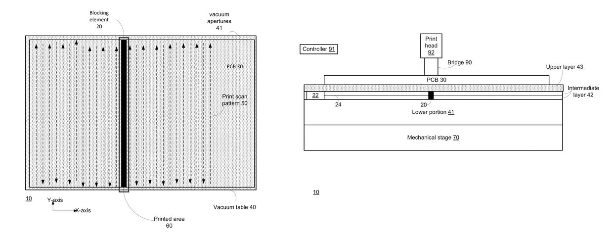
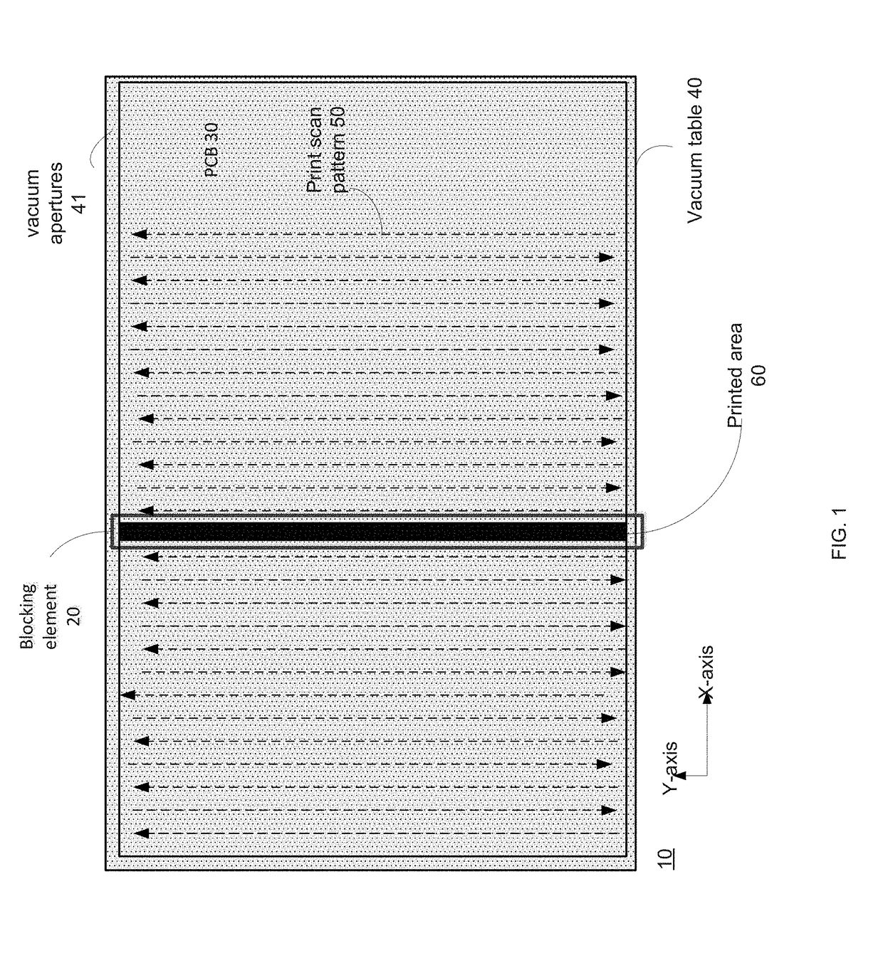
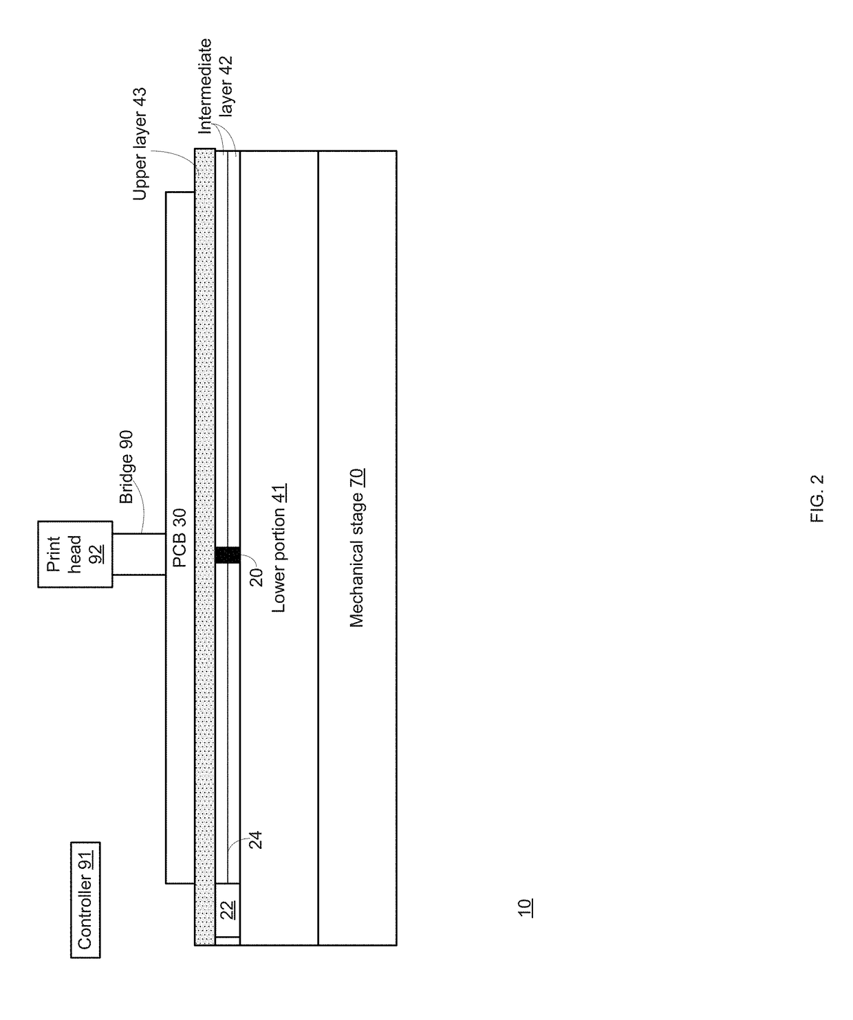
[0007]According to an embodiment of the invention there may be provided a system that may include a apertured structure that may be configured to support a substrate; a vacuum supply unit that may be configured to prevent a supply of vacuum to a first area of the substrate during a first processing period during which the first area may be processed and a second area of the substrate may be not processed; provide vacuum to the second area during the first processing period; prevent the supply of vacuum to the second area during a second processing period during which the second area may be processed and the first area may be not processed; and provide vacuum to the first area during the second processing period.
[0018]The method may include positioning the blocking module, by the positioning module and during the first processing period, at a first position thereby blocking a first conduit of the vacuum supply unit thereby preventing a supply of vacuum to the first area of the substrate; and positioning the blocking module, by the positioning module and during the second processing period, at a second position thereby blocking a second conduit of the vacuum supply unit thereby preventing a supply of vacuum to the second area of the substrate.

Problems solved by technology

When materials are layered near the multiple holes the vacuum of the holding table may induce the printing material towards the multiple holes and may even suck the printing material into the hole.

Method used


Image

  • Selective vacuum printing machine
  • Selective vacuum printing machine
  • Selective vacuum printing machine

Examples


Embodiment Construction

[0028]Because the apparatus implementing the present invention is, for the most part, composed of electronic components and circuits known to those skilled in the art, circuit details will not be explained in any greater extent than that considered necessary as illustrated above, for the understanding and appreciation of the underlying concepts of the present invention and in order not to obfuscate or distract from the teachings of the present invention.

[0029]In the following specification, the invention will be described with reference to specific examples of embodiments of the invention. It will, however, be evident that various modifications and changes may be made therein without departing from the broader spirit and scope of the invention as set forth in the appended claims.

[0030]In the following text there are provided various non-limiting examples of substrates and processing operations. The substrate may be a PCB, a wafer, a solar panel and the like. The processing operation...


PUM


Abstract

A system that may include a apertured structure that is configured to support a substrate and a vacuum supply unit that is configured to (i) prevent a supply of vacuum to a first area of the substrate during a first processing period during which the first area is processed and a second area of the substrate is not processed; (ii) provide vacuum to the second area during the first processing period; (iii) prevent the supply of vacuum to the second area during a second processing period during which the second area is processed and the first area is not processed; and (iv) provide vacuum to the first area during the second processing period.

Description

CROSS REFERENCE TO RELATED APPLICATIONS[0001]This application claims the priority of U.S. provisional patent 62 / 081,013 filing date Nov. 18, 2014 which is incorporated herein by reference.BACKGROUND OF THE INVENTION[0002]Different electronic substrates, such as printed circuit boards (PCBs) are manufactured by a complex manufacturing process during which various materials should be layered on the substrate by method of printing or any other known methods in order to produce electronic substrate such as PCB, wafer, die, flip-chip, etc. In addition, different electronic substrates may undergo repair processes or any other processes that require to place the substrate on a holding surface.[0003]During some stages of the manufacturing process or repair of the substrate process or any similar processes the substrate can be placed on a holding table such as a vacuum table. A vacuum table provides mechanical support to the substrate and also applies vacuum on the entire substrate in order ...

Claims


Application Information

Patent Timeline
Patent Type & Authority Patents(United States)
IPC IPC(8): B25B11/00H05K13/00H05K3/12
CPCB25B11/005H05K13/0061H05K2203/085H05K3/12
Inventor BEN-ABU, YEHUDA
Owner CAMTEK LTD
Why Eureka
Eureka Blog
Learn More