Eureka AIR delivers breakthrough ideas for toughest innovation challenges, trusted by R&D personnel around the world.

Compressor and method for operating the same

a compressor and compressor technology, applied in the field of compressors, can solve the problems of reducing the lifetime of the sliding portion of the compressor and the sealing member made of rubber or resin, generating frictional heat, and reducing the life of the sliding portion of the compressor and the sealing member, so as to prevent the supply of lubricating oil

Inactive Publication Date: 2009-03-19
TOYOTA IND CORP
View PDF16 Cites 0 Cited by
  • Summary
  • Abstract
  • Description
  • Claims
  • Application Information

AI Technical Summary

Benefits of technology

[0010]A second aspect in accordance with the present invention provides a method for operating a compressor which separates a lubricating oil from a refrigerant gas having a discharge pressure. The method comprises the steps of: opening or closing a throttle valve which is provided in the suction passage based on a differential pressure applied to a valve body of the throttle valve; flowing the separated lubricating oil to the suction passage upstream of the throttle valve; supplying the lubricating oil to a suction chamber through the throttle valve by opening of the throttle valve; and preventing supply of the lubricating oil to the suction chamber by closing of the throttle valve.

Problems solved by technology

If the lubricating oil is excessively supplied into the crank chamber, rotary elements of the compressor such as swash plate, and the like agitates the lubricating oil at a high speed, thereby generating frictional heat.
The frictional heat raises the temperature of the compressor, which may reduce the lifetime of the sliding portions of the compressor and sealing members made of rubber or resin.
Furthermore, after the operation of the compressor is stopped, the volume of the lubricating oil stored in the oil reservoir is small.

Method used


Image

  • Compressor and method for operating the same
  • Compressor and method for operating the same
  • Compressor and method for operating the same

Examples


Embodiment Construction

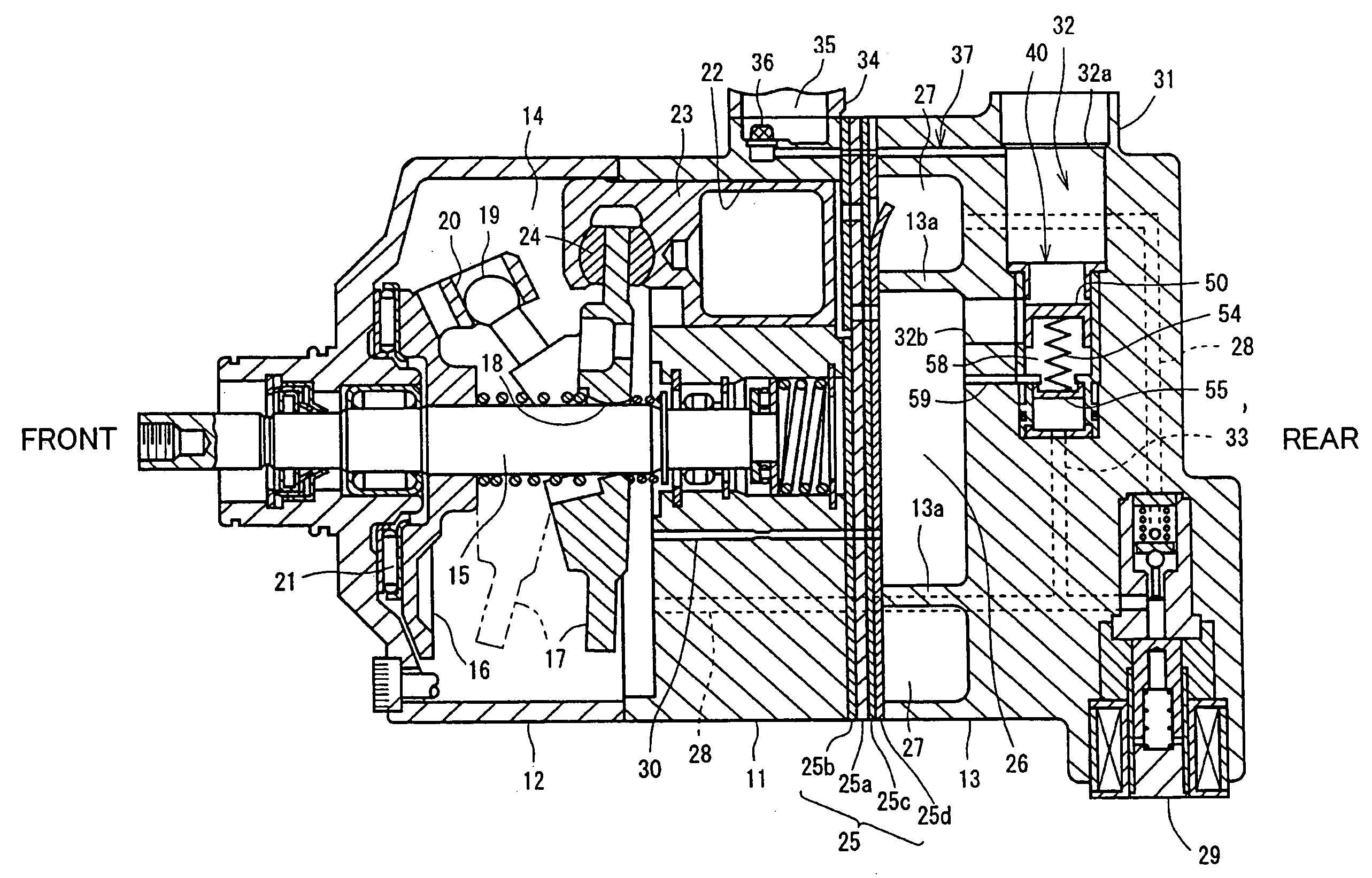
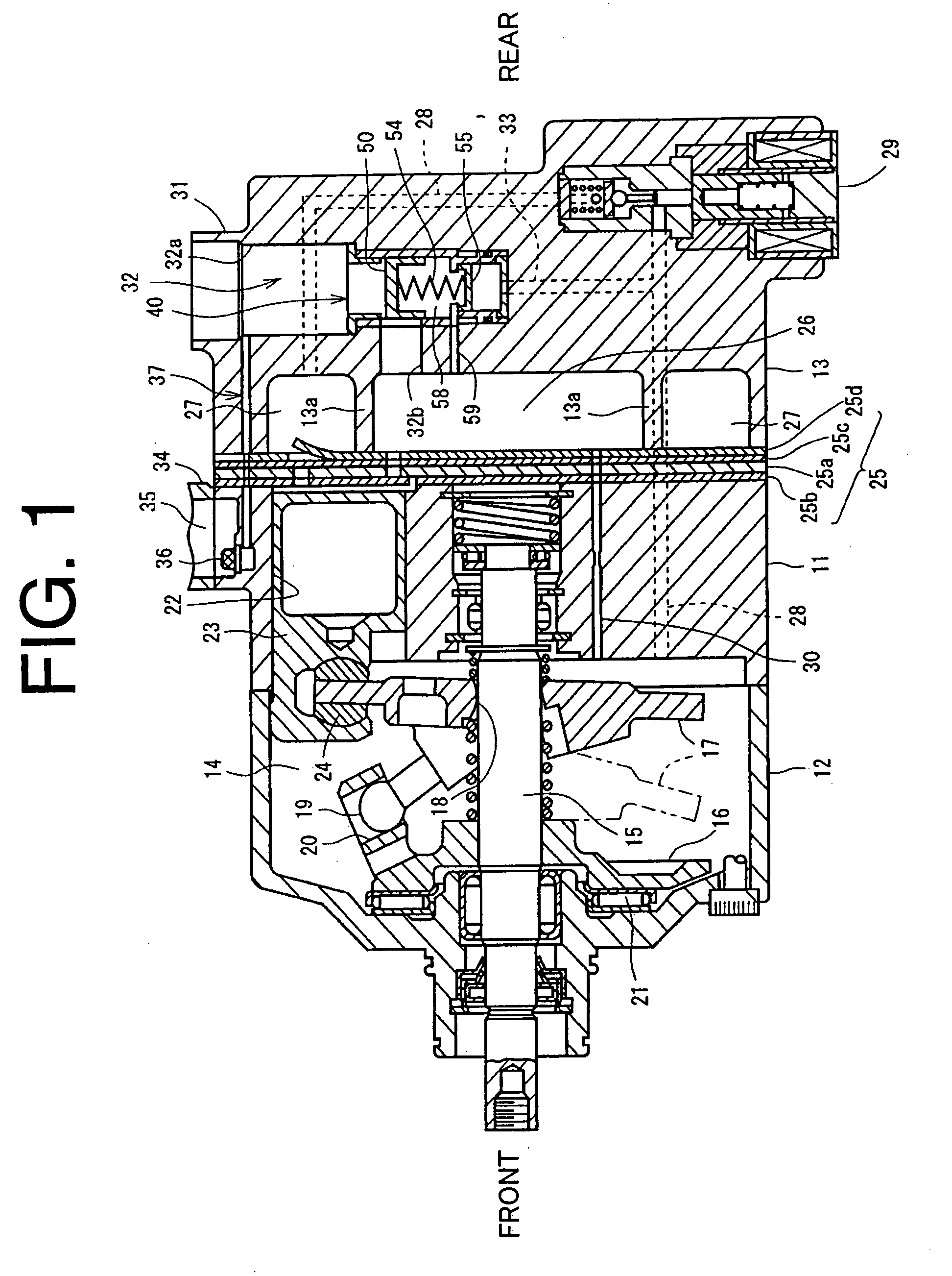
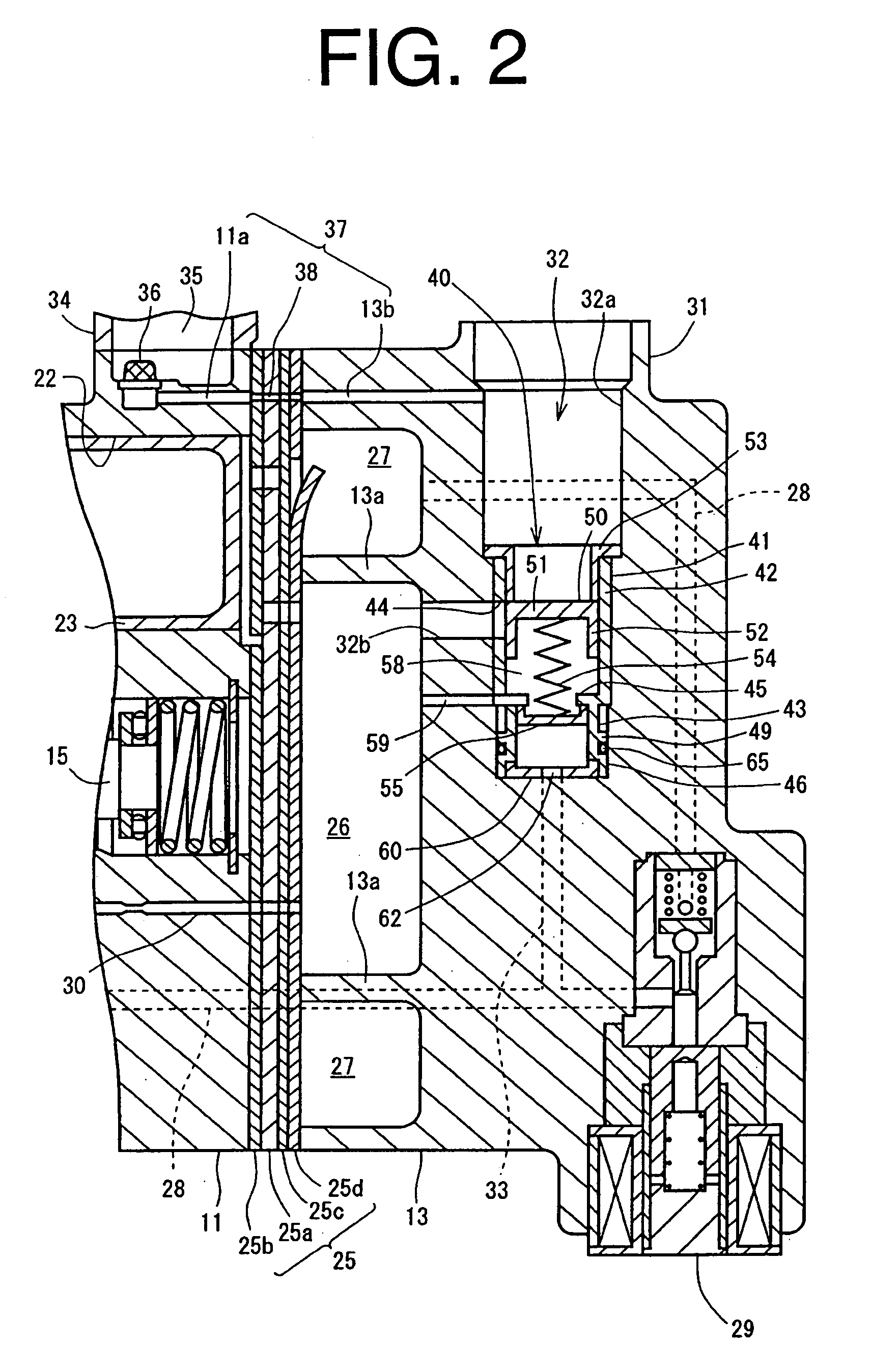
[0022]The following will describe a variable displacement compressor of a first preferred embodiment according to the present invention with reference to FIGS. 1 through 4. FIG. 1 is a longitudinal cross-sectional view of the variable displacement compressor of the first preferred embodiment according to the present invention, FIG. 2 is a partially enlarged cross-sectional view of the variable displacement compressor. FIG. 3 is a partially enlarged cross-sectional view of the variable displacement compressor showing the operation of a throttle valve and the flow of a lubricating oil when a displacement control valve is opened, and FIG. 4 is a partially enlarged cross-sectional view of the variable displacement compressor showing the operation of the throttle valve and the flow of the lubricating oil when the displacement control valve is closed. In FIG. 1, the left and right sides of the compressor on the drawing correspond to the front and rear sides, respectively.

[0023]Referring t...


PUM


Abstract

A compressor comprises a suction passage; an oil reservoir for storing a lubricating oil which is separated from a refrigerant gas having a discharge pressure; and a throttle valve provided in the suction passage and having a valve body for adjusting an opening degree of the suction passage based on a differential pressure applied to the valve body. The suction passage has an upstream suction passage which is located upstream of the throttle valve. The compressor comprises a lubricating oil passage connecting the oil reservoir to the upstream suction passage for the lubricating oil in the oil reservoir to flow to the upstream suction passage therethrough.

Description

BACKGROUND OF THE INVENTION[0001]The present invention relates to a compressor and a method of operating the same and more particularly to a compressor having a throttle valve which is provided in a suction passage which is in communication with a suction chamber and a method of operating the same.[0002]Unexamined Japanese Patent Application Publication No. 10-311277 discloses a refrigerant compressor, in which a lubricating oil in the form of mist is separated from a refrigerant gas having a discharge pressure to be stored in an oil reservoir before the refrigerant gas is delivered out of the compressor to an external refrigerant circuit. The stored lubricating oil is supplied into a crank chamber.[0003]During the entire operation of the compressor from a maximum displacement operation providing a maximum displacement to a minimum displacement operation providing a minimum displacement, the lubricating oil is constantly supplied from the oil reservoir into the crank chamber. Thus, ...

Claims


Application Information

Patent Timeline
Patent Type & Authority Applications(United States)
IPC IPC(8): F04B39/02
CPCF04B27/1036F04B39/04F04B27/109F04B27/0878F04B27/1018F04B27/1804F04B39/1073F05B2210/12F05B2210/14F25B43/02Y10S417/00
Inventor INOUE, YOSHINORIKOEDA, NAOKIKANAI, AKINOBUNAKAIMA, HIROYUKITARUTANI, TOMOJI
Owner TOYOTA IND CORP
Why Eureka
Eureka Blog
Learn More