Eureka AIR delivers breakthrough ideas for toughest innovation challenges, trusted by R&D personnel around the world.

Semiconductor memory device including array e-fuse

a memory device and semiconductor technology, applied in the direction of measurement devices, power supply for data processing, instruments, etc., can solve the problems of increased current consumption and increased current leakage, and achieve the effect of reducing power consumption

Active Publication Date: 2017-01-31
SK HYNIX INC
View PDF12 Cites 0 Cited by
  • Summary
  • Abstract
  • Description
  • Claims
  • Application Information

AI Technical Summary

Benefits of technology

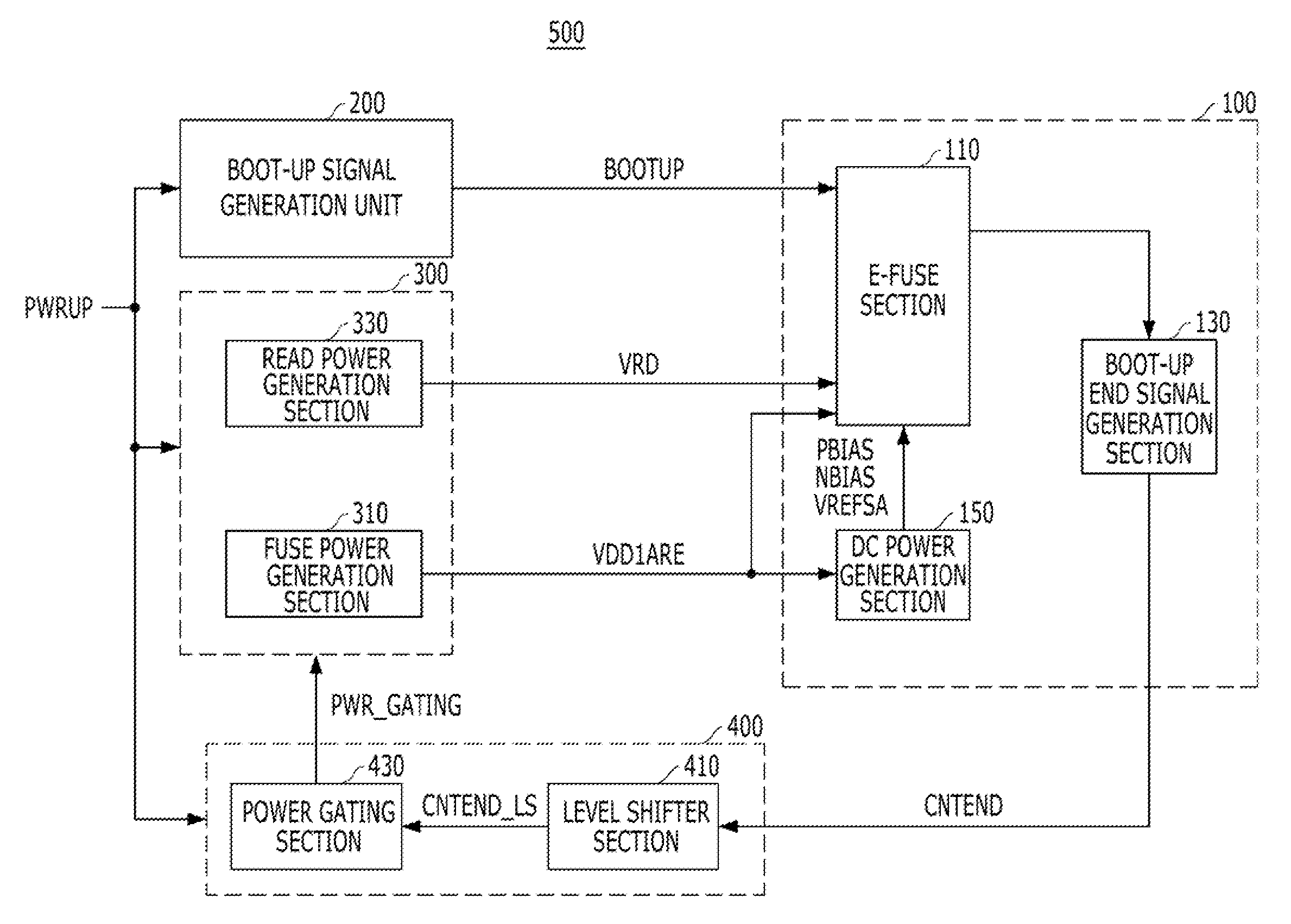
[0007]Various embodiments are directed to a semiconductor device having an array e-fuse and capable of reducing power consumption by preventing supply of a driving voltage to the array e-fuse after a boot-up operation.
[0009]In an exemplary embodiment, a method for driving a semiconductor device including an array e-fuse may include: generating a power-up signal when a boot-up operation starts, performing the boot-up operation by generating a plurality of driving voltages for the array e-fuse in response to the power-up signal, generating a boot-up end signal when a boot-up operation ends and preventing the generation of the driving voltages in response to the boot-up end signal.

Problems solved by technology

Therefore, when the semiconductor device includes transistors operating at a low voltage, that is, having low threshold voltages Vth, the semiconductor device may be operated at high speed, but current leakage may be increased.
As a result, since the current leakage increases during a normal operation of the semiconductor device, additional current consumption occurs when the array e-fuse is used.

Method used


Image

  • Semiconductor memory device including array e-fuse
  • Semiconductor memory device including array e-fuse
  • Semiconductor memory device including array e-fuse

Examples


Embodiment Construction

[0015]Various embodiments will be described below in more detail with reference to the accompanying drawings. The present invention may, however, be embodied in different forms and should not be construed as limited to the embodiments set forth herein. Rather, these embodiments are provided so that this disclosure will be thorough and complete and will fully convey the scope of the present invention to those skilled in the art. Throughout the disclosure, reference numerals correspond directly to the like parts in the various figures and embodiments of the present invention. It is also noted that in this specification, “connected / coupled” refers to one component not only directly coupling another component but also indirectly coupling another component through an intermediate component. In addition, a singular form may include a plural form as long as it is not specifically mentioned in a sentence.

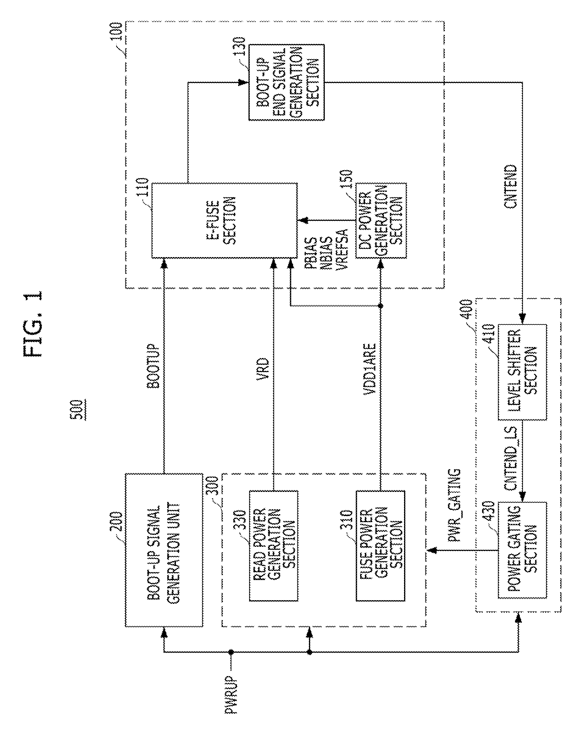
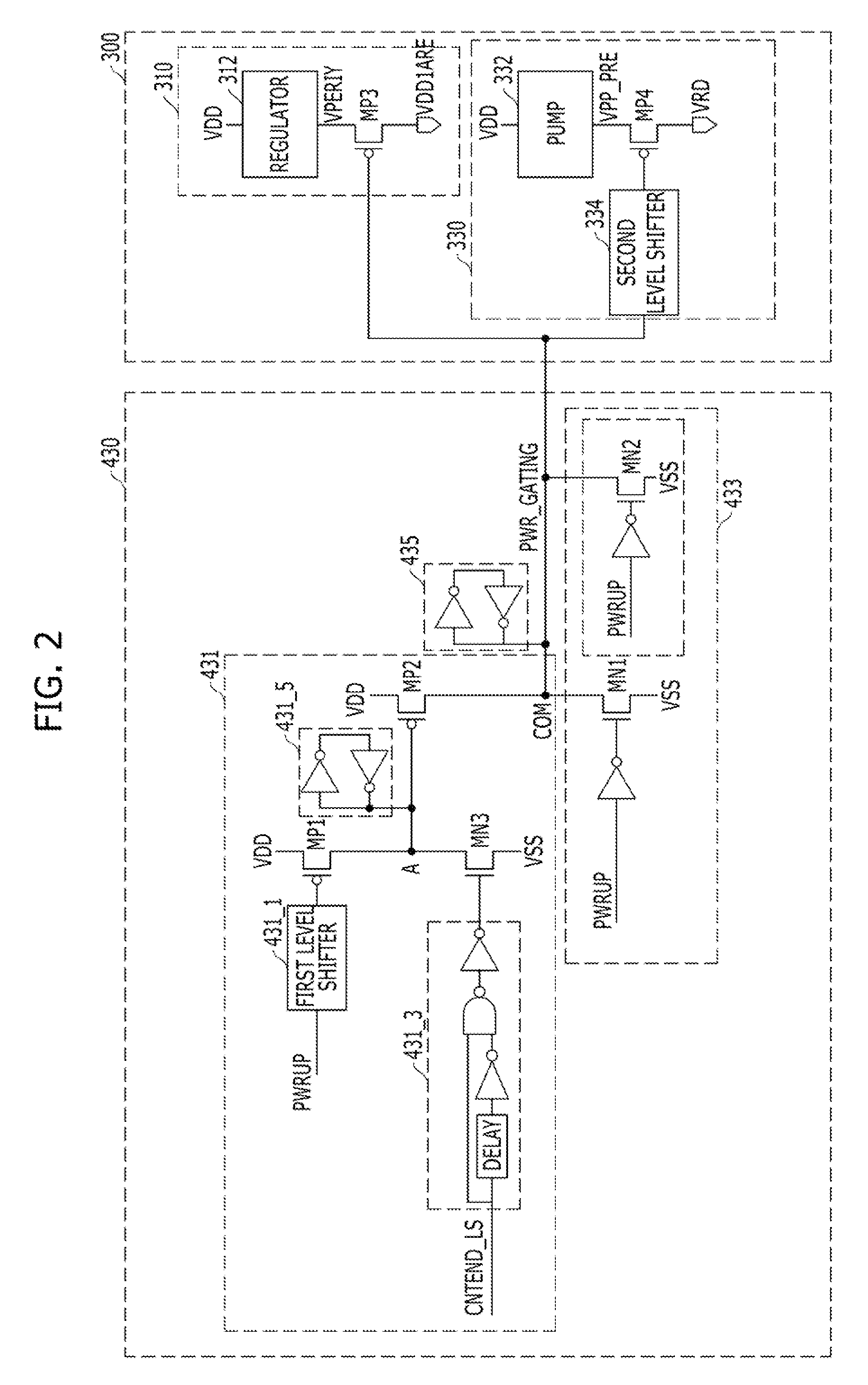
[0016]FIG. 1 is a block diagram illustrating a semiconductor device in accordance with ...


PUM


Abstract

A semiconductor device includes a fuse unit comprising an array e-fuse and suitable for generating a boot-up end signal when a boot-up operation ends, a power generation unit suitable for generating a plurality of driving voltages for the fuse unit in response to a power-up signal indicating start of the boot-up operation and a power control unit suitable for controlling the generation of the driving voltages in response to the power-up signal and the boot-up end signal.

Description

CROSS-REFERENCE TO RELATED APPLICATIONS[0001]The present application claims priority of Korean Patent Application No. 10-2013-0075068 filed on Jun. 28, 2013, which is incorporated herein by reference in its entirety.BACKGROUND[0002]1. Field[0003]Exemplary embodiments of the present invention relate to a semiconductor device having an array e-fuse, and more particularly, to a power gating technique for controlling power that is supplied to an array e-fuse.[0004]2. Description of the Related Art[0005]In general, each of a PMOS transistor and an NMOS transistor included in a dynamic random access memory (DRAM) has a threshold voltage Vth. Thus, an external voltage VDD equal to or more than 2*Vth corresponding to a sum of the threshold voltages of the PMOS transistor and the NMOS transistor should be basically secured to stabilize an operation region. Therefore, the DRAM requires a power-up signal generator to generate a power-up signal PWRUP indicating that the external voltage VDD rea...

Claims


Application Information

Patent Timeline
Patent Type & Authority Patents(United States)
IPC IPC(8): G06F1/26G06F1/32
CPCG06F1/26G06F1/32G11C5/14G11C29/00
Inventor HONG, YUN-SEOK
Owner SK HYNIX INC
Why Eureka
Eureka Blog
Learn More