
Image display device

a technology of image display and display screen, applied in the field of image display device, can solve problems such as uneven illumination, and achieve the effect of making bright spots less perceptibl

Active Publication Date: 2017-11-14
MITSUBISHI ELECTRIC CORP
View PDF26 Cites 6 Cited by
  • Summary
  • Abstract
  • Description
  • Claims
  • Application Information

AI Technical Summary

Benefits of technology

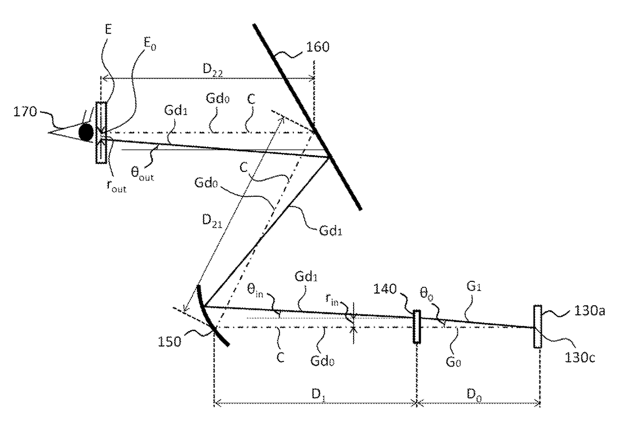
[0009]An image display device to provide an image perceivable from an area of an eye box, according to the present invention, includes a light source unit to emit a beam, a screen having a micro lens array on which multiple micro lenses are arranged, a scanning unit that has a mirror to reflect the beams emitted from the light source unit, and that swings the mirror around a pivot center to scan the beams over the screen, thereby generating the image on the screen, and an optical system to bring the image formed on the screen to the eye box, wherein an angle formed between a zero-order diffracted beam and a first-order diffracted beam, which are among a luminous flux of beams diffracted by the screen and pass through the eye box center, is smaller than a minimum visual angle.

Problems solved by technology

However, in a case where a sheet of the micro lens array is applied to a screen, the periodic structure of the micro lens array causes diffracted beams, resulting in a problem of luminance unevenness.

Method used


Image

  • Image display device
  • Image display device
  • Image display device

Examples


embodiment 1

1>

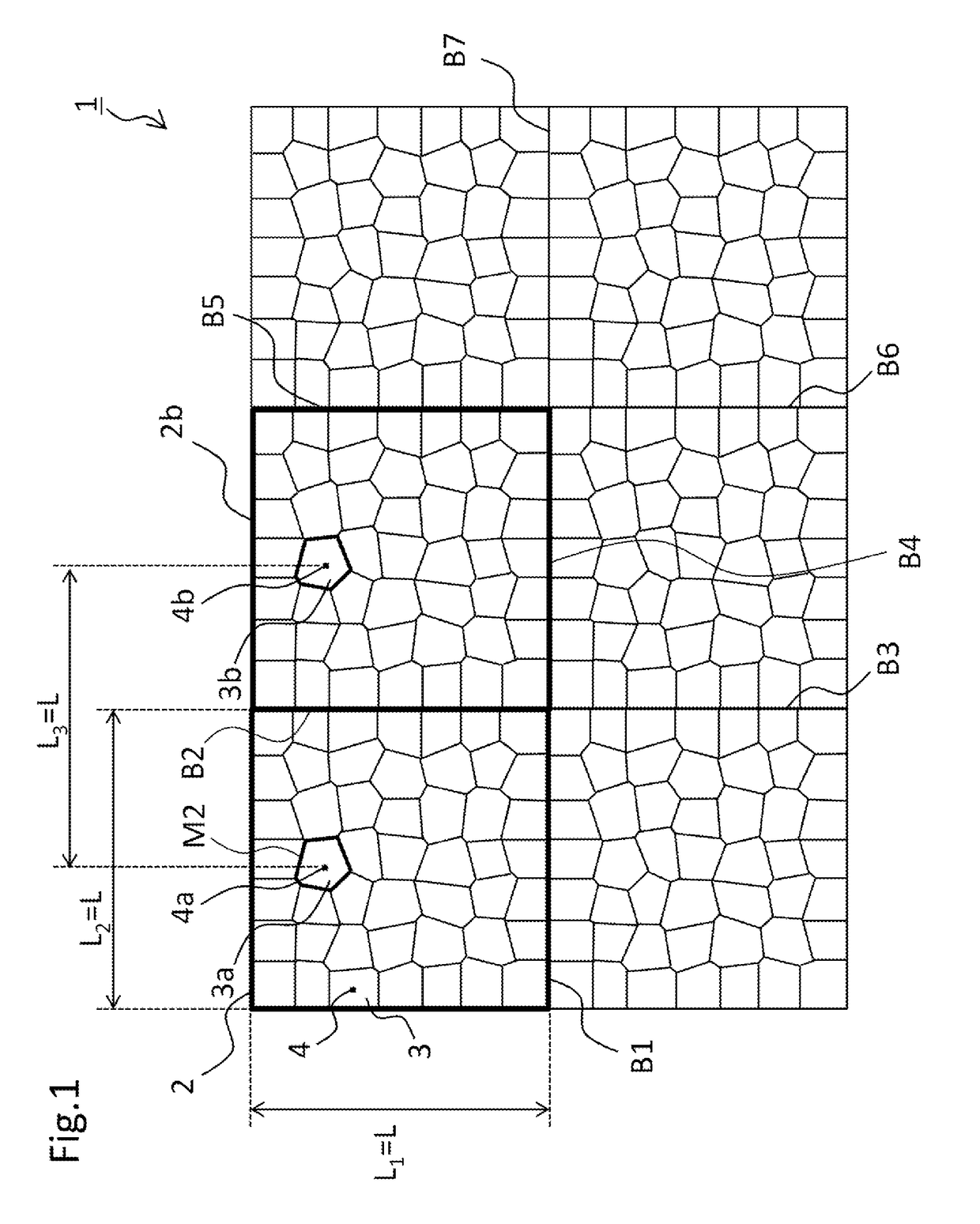
[0037]FIG. 1 is a drawing illustrating a micro lens array 1 according to Embodiment 1 of the present invention. As shown in FIG. 1 with bold rectangular frames, the micro lens array 1 includes multiple basic pattern lens groups 2.

[0038]The shape of the basic pattern lens group 2 is, for example, a rectangular with the longitudinal length L1 and the lateral length L2. FIG. 1 shows a case where the shape of the basic pattern lens group 2 is a square where L1=L2=L.

[0039]The micro lens array 1 shown in FIG. 1 has a configuration in which two basic pattern lens groups are longitudinally arranged and three basic pattern lens groups are laterally arranged. That is to say, in the micro lens array 1 shown in FIG. 1, the basic pattern lens groups 2 are arranged in 2×3.

[0040]The basic pattern lens group 2 are arranged adjoining to each other across the dividing lines B1 to B7. That is to say, the arrangement pattern according to which the micro lenses 3 in a basic pattern lens group 2 are po...

embodiment 2

[0237]In Embodiment 2, explanation will be made on the case where the screen 140 is disposed so as to be inclined by an angle θM to the optical axis C of the image display device 100 according to Embodiment 1.

[0238]In the case where the screen 140 is disposed so as to be inclined by the angle θM to the optical axis C of the image display device 100 according to Embodiment 1, FIG. 8 illustrates the optical path of an image beam, which emerges from the image display device 100 shown in FIG. 4, then is reflected by the windshield 160, and finally reaches the driver's eye 170.

[0239]In FIG. 8, omitted are the mirror 120, the light source unit 110, and the virtual image 180 which have been shown in FIG. 4. The other components shown in the figure also are in the same positional relation and the like as shown in FIG. 4. So, their explanation will be omitted. Also, in FIG. 8, the configurational components except for the screen 140 are in the same positional relation and the like as shown i...

embodiment 3

[0255]In Embodiment 3, a hexagonal lattice 21 (a regular hexagonal lattice) is adopted as the primitive lattice. Each of apexes 19 of micro lenses 18 is displaced from a lattice cell point 16 of the hexagonal lattice 21 by a predetermined displacement amount.

[0256]FIG. 10 is a drawing illustrating a micro lens array 14 according to Embodiment 3.

[0257]In FIG. 10, a basic pattern lens group 15 is indicated as a larger area out of two kinds of areas which are different in size and framed by bold lines. As shown in FIG. 10, a micro lens array 14 includes multiple basic pattern lens groups 15.

[0258]The micro lens array 14 has a configuration in which two basic pattern lens groups are arranged in the longitudinal direction and the three basic pattern lens groups are arranged in the lateral direction. Namely, the multiple basic pattern lens groups 15 are arranged in 2×3 longitudinally and laterally, respectively. The multiple basic pattern lens groups 15 are arranged adjoining to each othe...


PUM


Abstract

The image display device (100) provides images perceivable from the area of the eye box (E), and includes a light source unit (110), a screen (140), a scanning unit (130) and an optical system (155). The screen (140) has a single micro lens array (1) on which multiple micro lenses (3) are arranged. The scanning unit (130) includes a mirror (130a) to reflect beams emitted from the light source unit (110), and swings the mirror (130a) around a pivot center (130c) to scan the beams thereover, thereby generating images. The optical system (155) brings the images formed on the screen (140) to the eye box (E). An angle (θout) formed between a zero-order diffracted beam and a first-order diffracted beam, which are among a luminous flux of beams diffracted by the screen (140) and pass through the center of the eye box (E), is smaller than a minimum visual angle (Vmin).

Description

TECHNICAL FIELD[0001]The present invention relates to an image display device having a micro lens array as a screen for displaying an image.BACKGROUND ART[0002]A head-up display generates an image on a screen, for example, with a MEMS mirror. The image generated on the screen is emerging as image beams. The image beams are reflected by a reflection mirror etc. called a combiner, then magnified by a magnifying device etc., and finally are guided to the eye position or the eye point of the driver. The image generated on the screen is perceived from the eye point as a virtual image.[0003]There is a conventional technique proposed for a head-up display screen to use a micro lens array, which is composed of a large number of lenses periodically arranged. However, in a case where a sheet of the micro lens array is applied to a screen, the periodic structure of the micro lens array causes diffracted beams, resulting in a problem of luminance unevenness.[0004]Patent Document 1 therefore dis...

Claims


Application Information

Patent Timeline
Patent Type & Authority Patents(United States)
IPC IPC(8): G02B26/08G02B27/01G02B3/00
CPCG02B27/0101G02B3/0056G02B27/0149G02B2027/0154G02B2027/0118G02B2027/0145G02B2027/0114G02B3/0043G03B21/625
Inventor NAKAGAWA, NOZOMINAKAHARA, HIRONORIKISHIGAMI, TOMOTAKESHITA, NOBUO
Owner MITSUBISHI ELECTRIC CORP
Learn More