Supercharge Your Innovation With Domain-Expert AI Agents!

Control of electrically efficient LED arrays

a technology of led arrays and control circuits, applied in the field of module led lamps, can solve the problems of increasing the complexity and cost adding complexity to the design of led control circuits, and generating only high-quality images for machine vision systems

Active Publication Date: 2017-11-21
PROPHOTONIX
View PDF14 Cites 1 Cited by
  • Summary
  • Abstract
  • Description
  • Claims
  • Application Information

AI Technical Summary

Benefits of technology

[0016]The present invention comprises the provision and use of a modular LED lamp (e.g., backlight), and more particularly a modular LED lamp (e.g., backlight) comprising a current-regulating drive circuit for an LED strobe drive that can control the individual LEDs of the LED array. The invention uses one central processor which connects via shift register arrays to address each LED in a panel or series of panels. During the LED off-time, a pulse energy charging system is used to minimize the total input current required by the system during operation (i.e., during the LED on-time).

Problems solved by technology

Machine vision systems can only generate high quality images if the lighting used to inspect an object clearly defines the elements of the object which is being inspected.
This requirement for strobe (or pulse) control can add complexity to the design of the LED control circuitry when large numbers of LEDs are required.
This requires that the user have the ability to individually control the various LEDs used in the lamp, which can further increase the complexity and cost of the LED control circuitry.
Currently-available LED array systems are typically limited by a variety of issues.
By way of example but not limitation, currently-available LED array systems typically cannot address individual LEDs within the large LED arrays, are generally quite large and bulky, are typically complex, are typically inefficient, generally require large power supply units (e.g., in excess of one kilowatt) and are typically very expensive.
In these large LED array systems, the LEDs are typically placed in a series, or in parallel strings, which limits the controllability to individual strings (or “boards”) of LEDs.
The primary disadvantage of using a series configuration is that the output voltages can be very high when large numbers of LEDs are used.
However, the disadvantages of using a parallel configuration are power consumption in the balance resistors, non-uniformity of the optical output and lower system efficiency.
There are numerous strategies that can reduce the aforementioned issues, such as matrix-type configurations, but all of these strategies ultimately lead to increases in the size and cost of the LED array system.
Furthermore, many of these strategies are inefficient, inasmuch as they draw electrical power even when it is not required, by virtue of being powered continuously.
LED array systems that use strobing techniques to reduce the continuous power draw typically require large and expensive power supply units (e.g., >1 kilowatt).
This in turn requires the use of expensive (and large gauge) wiring and cabling which limits the flexibility and modularity of the overall LED array system.
However, for systems with a large number of LEDs, a single microcontroller is not able to balance the LED currents to the precision that is generally required.
Adding a microcontroller for each LED string (i.e., for each group of LEDs) generally leads to an unacceptable rise in costs and an increase in the space required for the LED control circuitry.
However, for large scale LED arrays, these techniques are not suitable.
However, in software implementations, the MCU is limited by clock speed and other factors.

Method used


Image

  • Control of electrically efficient LED arrays
  • Control of electrically efficient LED arrays
  • Control of electrically efficient LED arrays

Examples


Embodiment Construction

The LED Lamp (e.g., Backlight) in General

[0046]The present invention provides a series of design innovations to overcome issues with the prior art. This disclosure will primarily discuss the invention in the context of a monochromatic LED backlight configuration. However, it will be appreciated by those skilled in the art that the present invention can be applied to any LED array configuration, e.g., a line light, a ring light, etc. Furthermore, various types of LEDs can be accommodated with the present invention. For example, monochromatic, infrared or ultra-violet (UV) light sources can all be utilized without the need for any changes to the circuit hardware or infrastructure. LED forward voltages, drive currents, pulse widths, durations, etc. are all controlled by software.

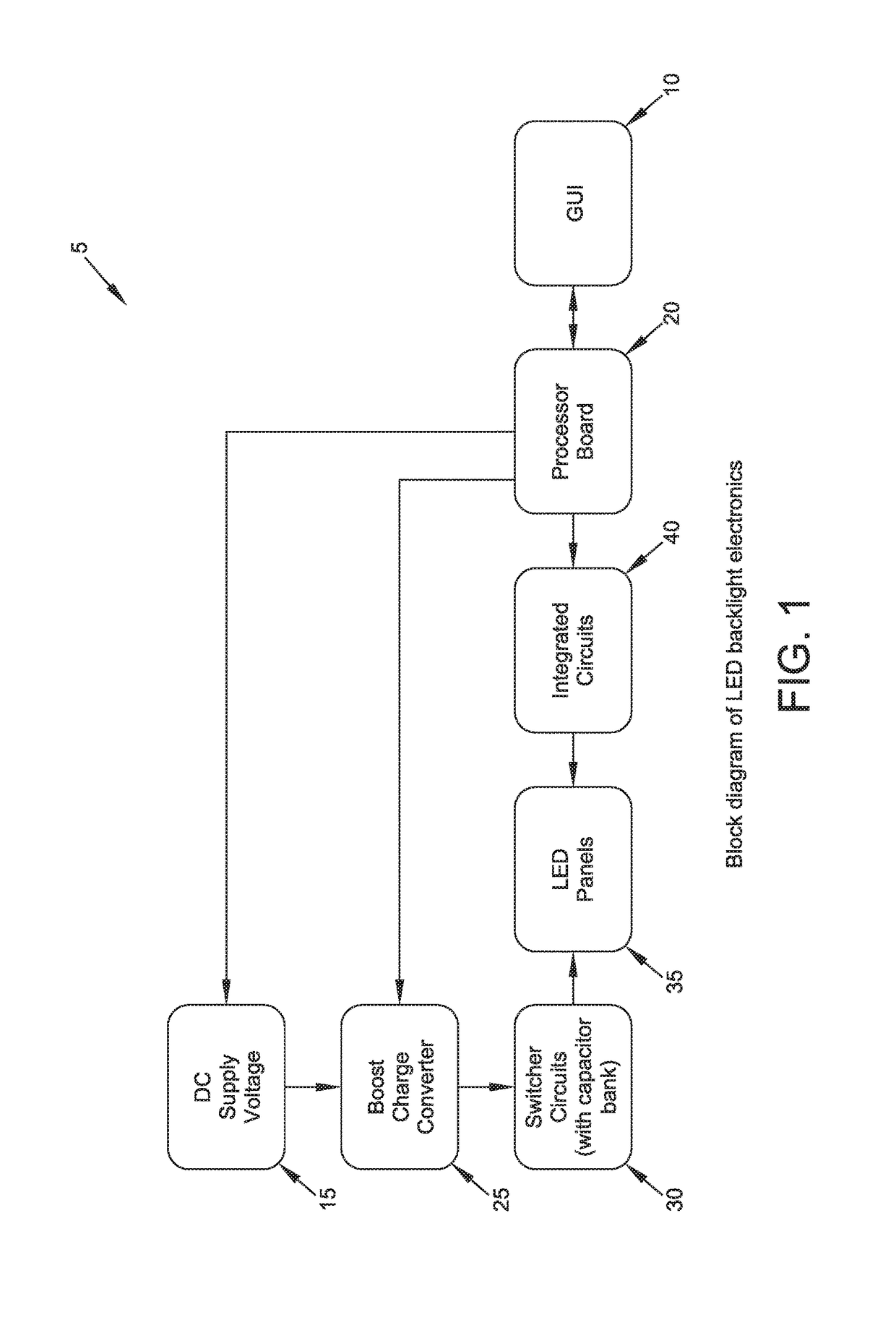
[0047]As shown in FIG. 1, a backlight 5 formed in accordance with the present invention may comprise seven basic elements: a GUI interface 10, a DC power supply 15, a processor printed circuit board (PCB) 20, a...


PUM


Abstract

An LED lamp comprising: a plurality of LED strings, each LED string comprising a plurality of LEDs; a plurality of constant current circuits for powering the plurality of LED strings, wherein one constant current circuit is provided for each LED string; a plurality of shift registers for controlling the operation of the plurality of constant current circuits, wherein at least one shift register is provided for each LED string; and a microprocessor for supplying timing pulses to the plurality of shift registers for controlling operation of the plurality of constant current circuits, the timing pulses comprising a plurality of serial bit streams.

Description

REFERENCE TO PENDING PRIOR PATENT APPLICATION[0001]This patent application claims benefit of pending prior U.S. Provisional Patent Application Ser. No. 62 / 251,332, filed Nov. 5, 2015 by ProPhotonix Limited and Peter Panek et al. for CONTROL OF ELECTRICALLY EFFICIENT LED ARRAYS, which patent application is hereby incorporated herein by reference.FIELD OF THE INVENTION[0002]This invention relates to lighting devices in general, and more particularly to a modular LED lamp (e.g., a backlight) and a current-regulating drive circuit for LED strobe operation that can control individual elements of the LED arrays of the lamp (e.g., the backlight).BACKGROUND OF THE INVENTION[0003]Machine vision is the technology used to provide imaging-based automatic inspection and analysis for applications such as parts inspection, process control, and robot guidance in industry. Employing the correct lighting is critical to creating a reliable, repeatable machine vision application.[0004]Currently, the li...

Claims


Application Information

Patent Timeline
Patent Type & Authority Patents(United States)
IPC IPC(8): G09G3/10H05B33/08H04N5/225H05B44/00
CPCH05B33/0827H05B33/0845H05B33/0815H04N5/2256H05B45/46H05B45/10H05B45/397Y02B20/30H04N23/56
Inventor PANEK, PETERO'CARROLL, PHILIP
Owner PROPHOTONIX
Features
  • R&D
  • Intellectual Property
  • Life Sciences
  • Materials
  • Tech Scout
  • Unparalleled Data Quality
  • Higher Quality Content
  • 60% Fewer Hallucinations
Learn More