Helmet or head mounted bicycle lights

a head-mounted, bicycle-mounted technology, applied in the direction of electric lighting with batteries, lighting and heating equipment, lighting support devices, etc., can solve the problems of affecting the light control of the switch, the top projection of the helmet is subject to damage and knocking off the helmet, and the helmet feels heavy. the effect of fast removal

Active Publication Date: 2017-11-28
LIGHT & MOTION INDS
View PDF7 Cites 23 Cited by
  • Summary
  • Abstract
  • Description
  • Claims
  • Application Information

AI Technical Summary

Benefits of technology

[0005]A system of bicycle lighting or head-mounted lighting of the invention includes front and rear lights connected by a cable and each being mountable on a bicycle helmet, headstrap or other headgear. The preferably red rear light has a casing that contains a rechargeable battery (although it could be non-rechargeable) and is positioned at a low position at the rear of the helmet (or on a headstrap). The separate front light assembly, without battery in primary embodiments, has a swivel-mounted casing (for up / down aim adjustment) on a base secured at a low position at the front of the head, and this casing includes the manual control for light power settings. The front lamp is powered by the rear casing battery, via the cable, in main embodiments. In one variation the front assembly plugs into the rear assembly but also contains its own rechargeable battery so that it can be used independently for short durations. The battery in front can be recharged by the rear light casing battery, or by a wall charger.
[0006]Mounting brackets for each of the front and rear lights are easily secured to opposed positions on the helmet or headstrap and can remain in place, with the light casings themselves being quickly removable from the brackets for recharging or for security. The front mount includes a backing, enabling the front light to be mounted over either a rib or a vent of a helmet.
[0007]An important feature of the invention is that the primary weight of the light system is mounted low at the rear of the helmet or headgear, in the casing that holds the red rear light or lights, with the front light also mounted low on the helmet or headstrap and powered through a cable connected to the rear of the casing. Controls are conveniently positioned on the front light, controlling both the front and rear lights as to power and flash status. Another important feature is that the front light includes an amber light providing side lighting toward both sides, thus providing for 360° visibility of the rider. The amber side light can also be included on the rear light.
[0012]The front and rear lights can easily be attached to a helmet (or a headstrap if similar base elements are used) even with the helmet on the user's head. The quick connect / disconnect attachments to the base allow for attachment by feel.
[0013]It is therefore among the objects of the invention to improve over prior head worn night lights, through the provision of a front and rear lighting system easily attachable to a helmet or headstrap and mounted at low positions at front and rear of the head, with quick removal of the lights from a helmet, versatility in use, convenient recharging, and minimal total weight. These and other objects, advantages and features of the invention will be apparent from the following description of a preferred embodiment, considered along with the accompanying drawings.

Problems solved by technology

Such lights positioned at a high point on top of the rider's helmet put considerable weight at a high location, tending to make the helmet feel top heavy.
In addition, this top projection on the helmet is subject to being damaged and knocked off the helmet by objects such as tree branches.
Switch control of the light is not convenient when riding.

Method used


Image

  • Helmet or head mounted bicycle lights
  • Helmet or head mounted bicycle lights
  • Helmet or head mounted bicycle lights

Examples


Embodiment Construction

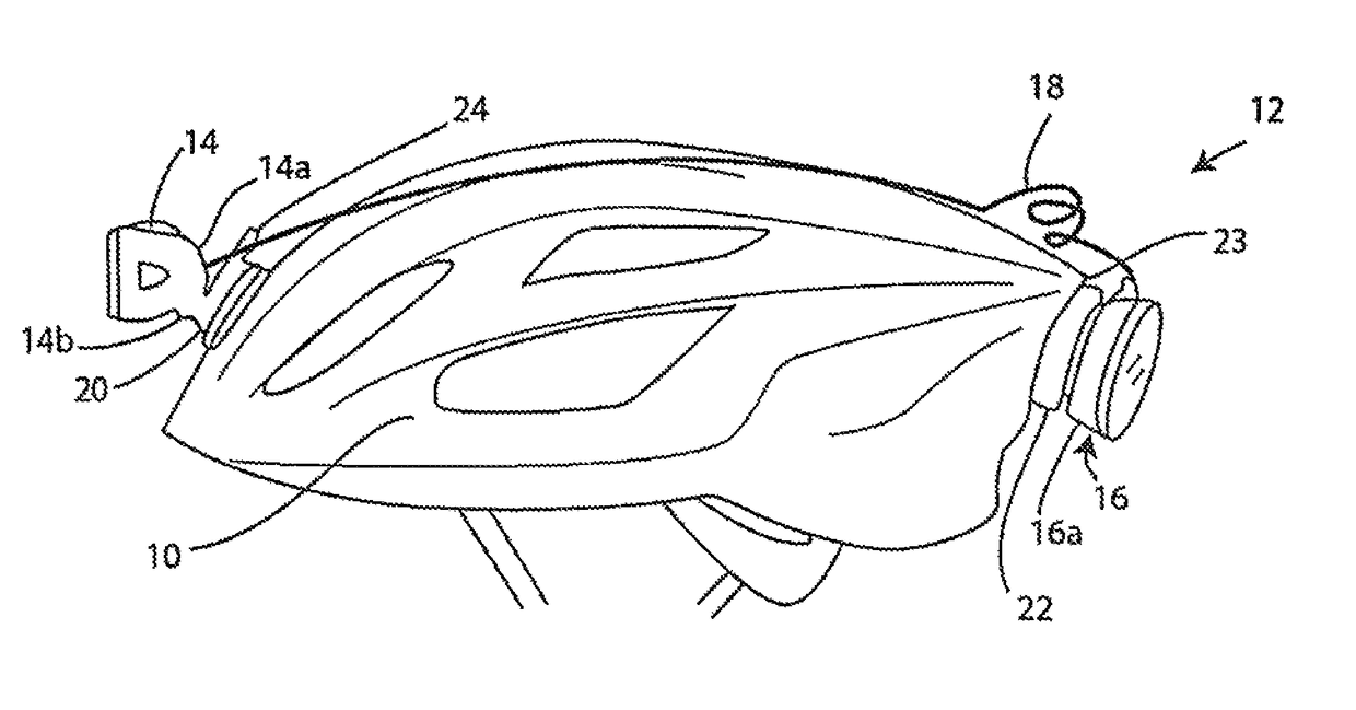
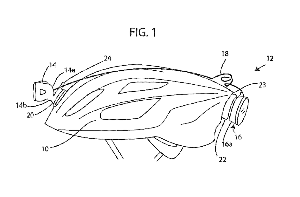
[0026]In the drawings, FIG. 1 shows a bicycle helmet 10 on which the lighting system 12 of the invention is mounted, in a preferred embodiment. The lighting system 12 includes a front-mounted forward light assembly 14 and a rear-mounted light assembly 16 that also contains a battery or batteries for both the front and rear lights. The rear light assembly 16 connects to the front light 14 by a small cable 18. As seen in the drawing, each of the light assemblies has a housing or housing assembly 14a, 16a, that connects to a base 20, 22, respectively, these bases being secured by straps to the helmet 10. The straps are passed through openings in the helmet at or near the front and rear, with the bases 20, 22 bearing against helmet structure between openings. The bases 20 and 22 are mounted at positions low on the helmet, for a low center of gravity, particularly the rear light assembly 16 that includes the battery or batteries, which are a large portion of the weight of the entire asse...


PUM


Abstract

A bicycle light system has front and rear (white and red) lights with mounting brackets to secure on a bicycle helmet. A battery is contained in the rear light casing, with an electrical cord extending between the front and rear light casings. The front light casing has controls for both front and rear lights, which can include different power levels and preferably a flash mode for the front light. Helmet or headstrap mountings for the front and rear light casings have a quick-release feature enabling the lights to be easily and quickly removed from the helmet or headstrap, such as for recharging. Multiple selectable lights can be included in the front light assembly. In an embodiment, any of a series of different front light assemblies can be plugged into the rear assembly. For marine use appropriate light colors can be provided.

Description

[0001]This application is a continuation-in-part of application Ser. No. 13 / 374,003, filed Dec. 6, 2011, now U.S. Pat. No. 8,733,989, which was a continuation-in-part of application Ser. No. 12 / 799,082, filed Apr. 16, 2010 and issued Dec. 6, 2011 as U.S. Pat. No. 8,070,308.BACKGROUND OF THE INVENTION[0002]This invention concerns lighting for bicycles and other uses, and especially a compact set of front and rear lights to be mounted on the bicycle rider's helmet or on a headstrap or other headgear.[0003]Bicycle riders have had a wide array of different options for night lighting, both to illuminate the path ahead and to warn those behind in vehicles or on other bicycles, using a red rear-facing light. These have included handlebar-mounted front lights, including high-powered lights connected to battery packs secured to bicycle frame bars, lower-powered head lamps that mount on handlebars with batteries contained in the light housing, and some lights provided for mounting on the ride...

Claims


Application Information

Patent Timeline
Patent Type & Authority Patents(United States)
IPC IPC(8): F21V21/084
CPCF21V21/084A42B3/044A42B3/0446F21L2/00F21L4/08F21V21/0885F21V23/0414F21V23/06
Inventor MCCASLIN, CHRISTOPHEREMERSON, DANIEL T.MASEK, JR., THEODORE DALEROBERTSON, BEAU JESSE
Owner LIGHT & MOTION INDS
Why Eureka
Try Eureka