
Methods and devices for counteracting stresses during 3D printing

a stress-resistance and 3d printing technology, applied in the field of 3d printing, can solve the problems of difficult removal, brims can be difficult to remove, and defects on the surface of the 3d printed object from which it is removed, so as to reduce or eliminate surface defects, the effect of easy removal

Active Publication Date: 2017-12-05
3D SYST INC
View PDF4 Cites 0 Cited by
  • Summary
  • Abstract
  • Description
  • Claims
  • Application Information

AI Technical Summary

Benefits of technology

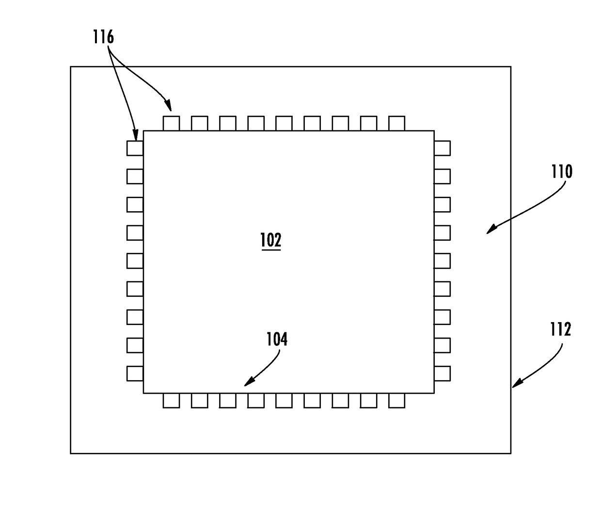
[0011]The various embodiments of the present invention address the above needs and achieve other advantages by providing a 3D printing device that contacts the perimeter of the 3D printed object with a perforated interface to counteract stresses in the 3D printed object that might otherwise cause the 3D printed object to curl or warp. The perforated interface enables the sidewalk to be removed much more easily than prior art 3D printed devices, such as rafts, anchors, and brims, and the perforated interface reduces or eliminates surface defects on the 3D printed object as compared to prior art 3D printed devices for counteracting stresses.

Problems solved by technology

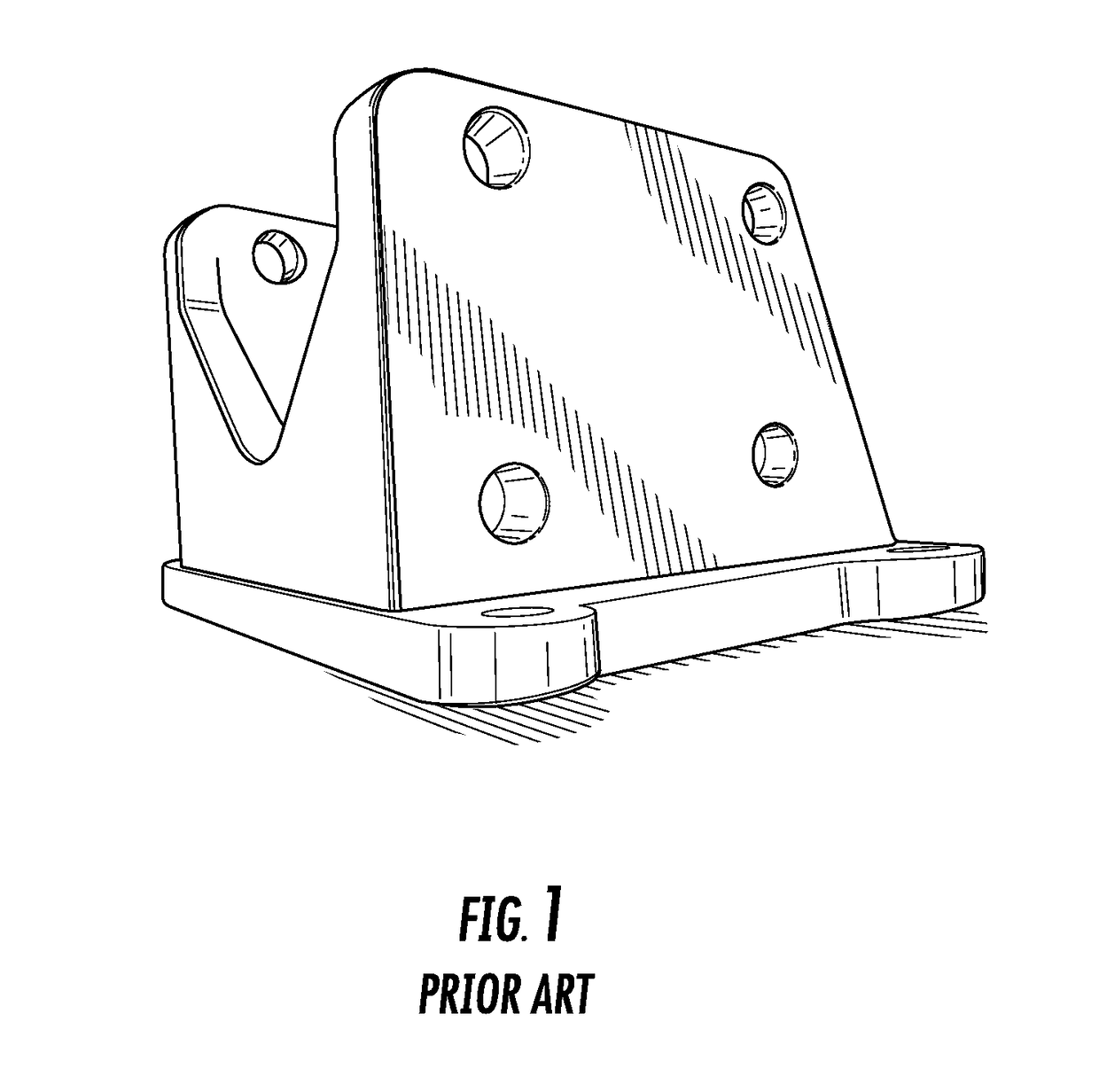
However, such rafts are difficult to remove from the 3D printed object, particularly if the raft and 3D printed object are made from the same build material, and rafts typically leave undesirable defects on the surfaces of the 3D printed object that contacted the raft, and those features must be cut, sanded off, or otherwise removed or hidden.
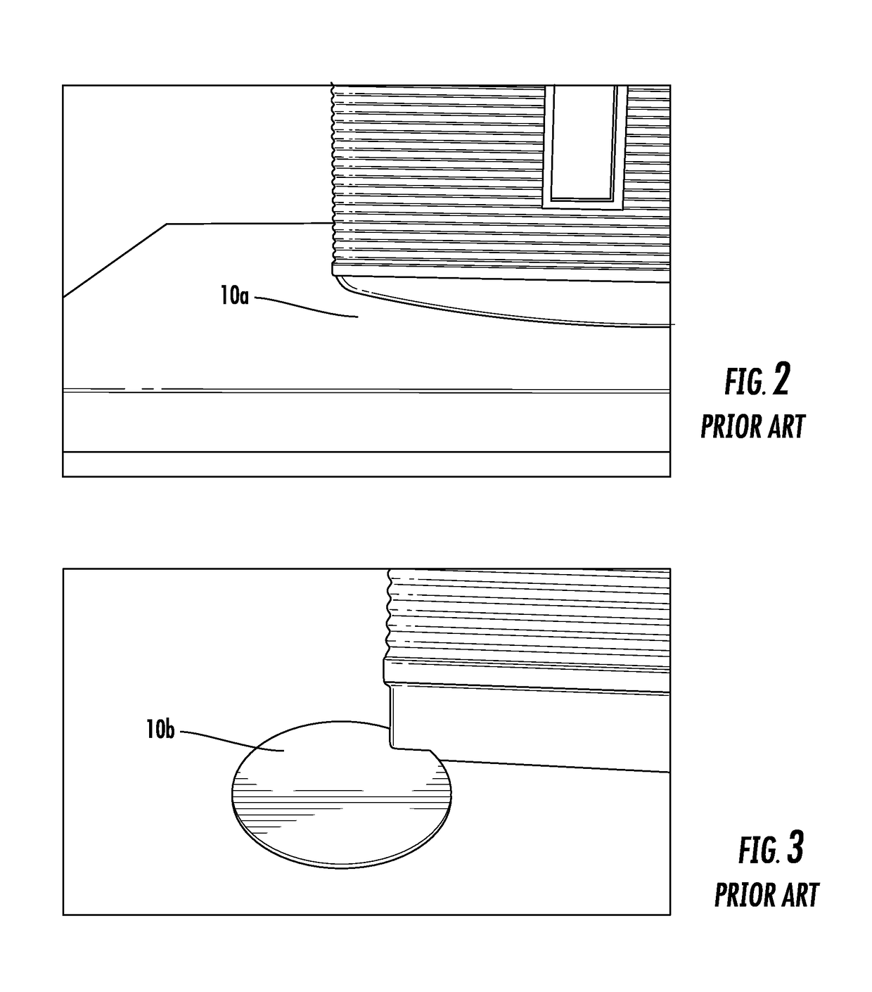
One disadvantage of using anchors is they may be difficult to remove and can leave defects on the surface of the 3D printed object from which it is removed.
Similar to anchors, brims can be difficult to remove and can leave defects on the surface of the 3D printed object caused by the removal of the brim from the 3D printed object.
For example, sometimes knives, box cutters, or other handtools may be required to remove an anchor or brim, which can be dangerous for the user and can leave flaws or other defects on the surface of the 3D printed object.

Method used


Image

  • Methods and devices for counteracting stresses during 3D printing
  • Methods and devices for counteracting stresses during 3D printing
  • Methods and devices for counteracting stresses during 3D printing

Examples


example 1

Methods of 3D Printing an Object with Reduced Curl

[0063]A variety of 3D printed objects along with corresponding skirts (comprising a sidewalk and a perforated interface) were produced consistent with methods described herein. The resulting 3D printed objects and skirts were then tested to determine the tensile strength of various configurations of perforated interfaces. 3D printed objects were produced having varied connector-to-gap or contact-to-gap ratios. The ratios used are described further herein below. FIGS. 7A-7E illustrate tensile strength testing equipment, protocol, and data.

[0064]Specifically, FIG. 7A illustrates in schematic form the tensile forces (TF) applied to the 3D printed object (102) and the sidewalk (112). An upward force was applied to the sidewalk (112), and a downward force was applied to the 3D printed object (102), and the total force required to propagate a tear along the perforation was measured. FIG. 7B illustrates the actual test fixture for the Type-...


PUM

PropertyMeasurementUnit
angleaaaaaaaaaa
angleaaaaaaaaaa
widthaaaaaaaaaa

Abstract

Methods of 3D printing an object with reduced curl on at least one surface that contacts a print plate are described herein. For example, in some embodiments, a method of 3D printing an object comprises depositing build material to form a first layer of a 3D printed object and depositing build material in a predetermined pattern to form a first layer of a skirt in contact with the 3D printed object. Depositing build material to form the first layer of the skirt comprises 3D printing a first layer of a sidewalk that substantially surrounds at least a portion of a perimeter of the 3D printed object and 3D printing a first layer of a perforated interface between the sidewalk and the perimeter of the skirt.

Description

CROSS REFERENCE TO RELATED APPLICATION[0001]This application claims priority pursuant to 35 U.S.C. §119(e) to U.S. Provisional Patent Application Ser. No. 62 / 080,007, filed on Nov. 14, 2014, the entirety of which is incorporated herein by reference.FIELD OF THE INVENTION[0002]The present invention is related to 3D printing and other additive manufacturing processes for creating physical objects, and more particularly, to methods, systems, devices, and designs that prevent warping of physical objects while they are being made by 3D printing or other additive manufacturing processesBACKGROUND OF THE INVENTION[0003]Digital designs can be made into physical objects by 3D printing, which is also known as additive manufacturing. 3D printing typically comprises depositing or fusing materials in a layer-by-layer manner to create cross-sections of the 3D printed object. Because deposited or fused material may undergo stresses as the material changes temperature, chemical composition, crystal...

Claims


Application Information

Patent Timeline
Patent Type & Authority Patents(United States)
IPC IPC(8): B29C67/00B29C64/40B33Y10/00B33Y40/00
CPCB29C64/106B33Y10/00B29C64/40B33Y40/00B29C64/118
Inventor HERRAN, LEIGHMOUSSA, KHALILJOHNSON, MARTIN ALANPODGURSKY, NICKALAUS K.MANNERS, CHRIS ROBERTSWILKES, TERRYREILLY, JENNY
Owner 3D SYST INC
Learn More