
Lighting device for attachment to a tool

a technology of lighting device and tool, which is applied in the field of lighting devices, can solve the problems of burning the user and/or patient, the lighting device that includes the cost of known lighting devices that include the integral form of the light source, etc., and achieves the effect of convenient attachment to the tool and detachable from the tool, efficient and easy assembly and us

Active Publication Date: 2017-12-26
PATHY MEDICAL LLC
View PDF153 Cites 27 Cited by
  • Summary
  • Abstract
  • Description
  • Claims
  • Application Information

AI Technical Summary

Benefits of technology

The invention is a lighting device that is more compact, easy to attach and detach from a tool, and can be securely attached to the tool at various points. The device can also illuminate a light source simultaneously when attached to the tool, ensuring efficient and easy assembly and use. Overall, the invented tool lighting device is more practical and convenient than previous devices.

Problems solved by technology

For example, known lighting devices that include a light source integrally formed therein are generally expensive, bulky, and can cause injury.
Known cordless and corded lighting devices add significant bulk to a tool preventing a user from manipulating the tool with the precision required in many situations and being able to extend the tool into tight spaces.
Additionally, many lighting device, especially corded lighting devices, require constant repositioning, are cumbersome, are assistant-dependent to hold or re-position, and can be disruptive to a surgical field.
Further, corded lighting devices as well as light sources integrally formed within a tool can become hot, burn the user and / or the patient, and possibly even cause a fire.
However, similar to lighting devices, headlights are bulky, commonly require cables to connect to a power source, require constant readjustment, and can pose a potential safety hazard.
Moreover, being worn on the head, they are at a distance from the surgical field, decreasing their effectiveness, and can be cumbersome to the user, and cause fatigue if worn for an extended period of time.

Method used


Image

  • Lighting device for attachment to a tool
  • Lighting device for attachment to a tool
  • Lighting device for attachment to a tool

Examples


Embodiment Construction

[0033]The present invention now will be described more fully hereinafter with reference to the accompanying drawings, in which embodiments of the invention are shown. The invention may, however, be embodied in many different forms and should not be construed as limited to the embodiments set forth herein. Like numbers refer to like elements throughout.

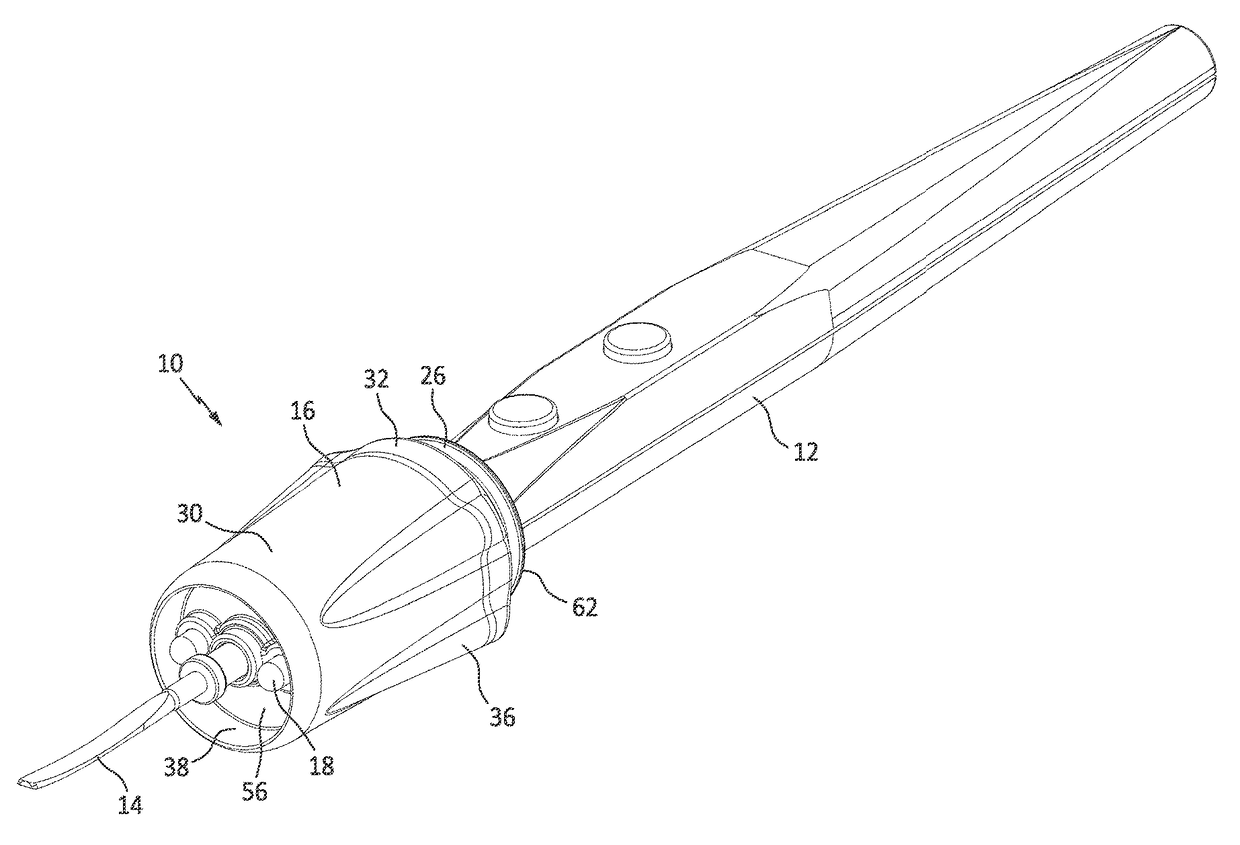
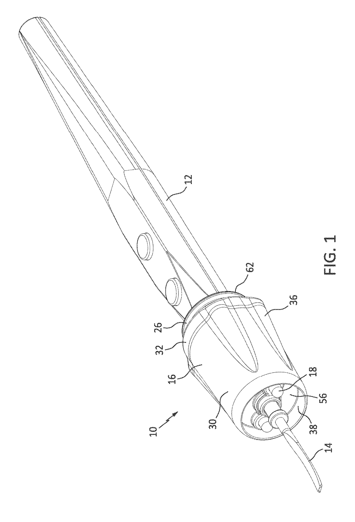
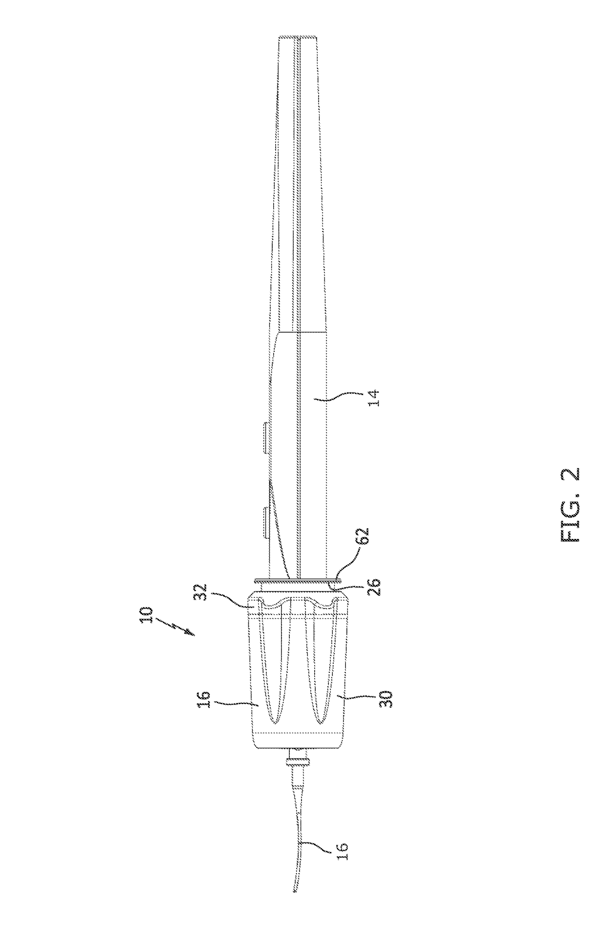
[0034]As shown in an embodiment in FIGS. 1 and 2, a cordless lighting device, indicated generally by the reference numeral 10, is installed onto and over a portion of a distal end of the tool 12 and is removably thereto. A shaft 14 of the tool 12 can subsequently extend through an opening extending from a proximal end to a distal end of the lighting device 10 so that the device 10 surrounds the tool 12. In the illustrated embodiment, the tool 12 is a BOVIE® pen, and the shaft 14 the blade of the BOVIE® pen. However, the present invention may be installed upon various different types of tools, both surgical and non-surgical, of various ...


PUM


Abstract

A cordless light attachment for a tool includes a housing that has a proximal end and a distal end, and an interior cavity that extends from the proximal end to the distal end, forming an opening extending through the housing from the proximal end to the distal end. The device receives therein a tool and removably attaches to the tool. The device has at least one light source powered by a cordless power source arranged on or within the housing.

Description

CROSS-REFERENCE TO RELATED APPLICATIONS[0001]The patent application claims benefit under 35 U.S.C. §119(e) to U.S. provisional application Ser. No. 61 / 853,232, filed Apr. 1, 2013, titled “Operative Instrument Light Attachment,” which is hereby expressly incorporated by reference as part of the present disclosure.FIELD OF THE INVENTION[0002]The present invention relates to a lighting device. More particularly, the invention relates to a wireless lighting device that is attachable to a tool or object.BACKGROUND OF THE INVENTION[0003]A lighting device is used to allow an operator to illuminate, and thus more precisely control and enhance, a space or area with a lighted field of view. In many situations, a lighting device can be used to illuminate a closed or confined space that would not regularly receive an adequate amount of light, if at all. Existing lighting devices are connectable to a variety of tools, including, for example, medical devices and screwdrivers, to illuminate the ar...

Claims


Application Information

Patent Timeline
Patent Type & Authority Patents(United States)
IPC IPC(8): F21V33/00F21L4/02A61B90/30A61B18/14
CPCF21L4/02A61B90/30F21V33/0084F21V33/0068A61B2090/309A61B18/1402A61B90/35A61B90/50
Inventor PATHY, VINOD V.
Owner PATHY MEDICAL LLC
Learn More