Riser release flaring system for parafoils

a technology of release flaring and parafoil, which is applied in the field of flight, can solve problems such as the challenge of flight vehicles, and achieve the effects of reducing the descent rate of flight vehicles, increasing internal pressure, and increasing capacity

Active Publication Date: 2018-01-16
WORLD VIEW ENTERPRISES
View PDF73 Cites 12 Cited by
  • Summary
  • Abstract
  • Description
  • Claims
  • Application Information

AI Technical Summary

Benefits of technology

[0006]Various embodiments of the technology generally relate to systems to slow the landing of a descent system, such as a parafoil, and / or decrease the landing speeds of payloads delivered by the descent system. Decreasing the landing speeds of descent systems could greatly reduce landing loads and enable the delivery of more sensitive payloads.
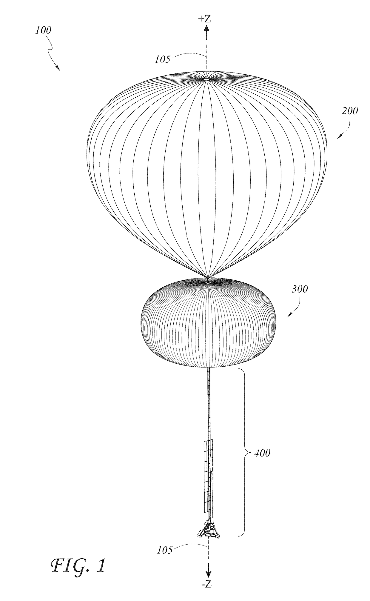
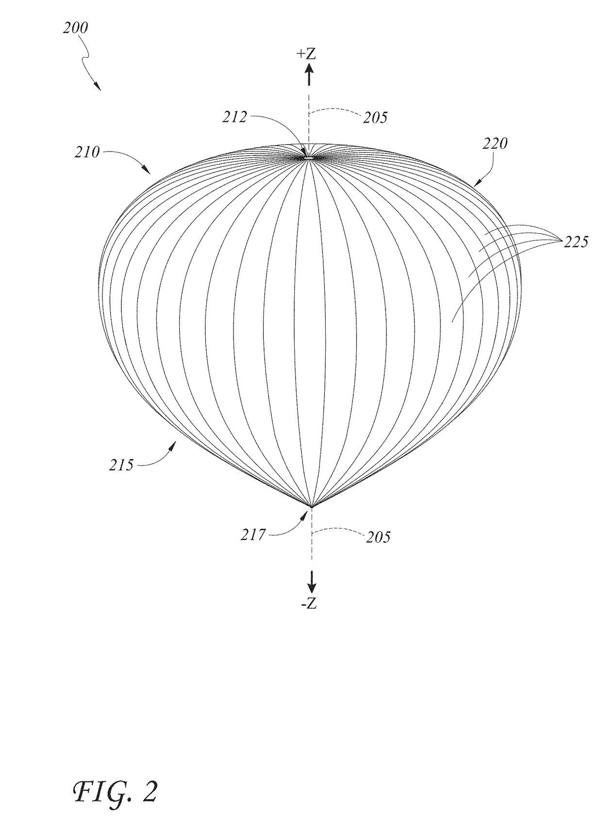
[0008]The riser release system may be used with an LTA system, such as a tandem balloon system. A zero-pressure balloon (ZPB) is attached in tandem with a variable air super-pressure balloon (SPB). The ZPB provides lift for the system while the SPB provides a variable amount of ballast by pumping in or expelling out ambient air. By dividing the two functions among the two separate balloons, each balloon and its associated accessories are configured for the respective balloon's particular function, allowing achievement of advanced performance targets with the LTA. For instance, a compressor provides air to the SPB and can be configured for providing a sufficient rate and volume of air at particular high altitudes in which the LTA system will be flown. Such compressor designs allow for rapid descent, as well as high pressures within the SPB which allows for rapid venting and ascent, both of which can be performed at high altitudes. As further example, configurations of the SPB skin and accompanying tendons allow for a structurally efficient and stable SPB. For instance, the SPB may be configured to assume a “pumpkin” shape during flight capable of withstanding very large internal pressures, while also providing stability to prevent issues such as deformation of the skin, including “S-clefting.” These and other features of the LTA system provide the ability to both simultaneously achieve high altitude (e.g. at or above about 50,000 feet) and actively control altitude over a meaningful range (e.g. more than about 20,000 feet).
[0009]These and other features provide an LTA platform that can be scaled and configured simply for various missions and flight requirements and with safe delivery and landing of a payload using the riser release system. For instance, the basic design of the LTA system can be configured for higher altitude and / or heavy lift missions with a higher capacity multi-stage compressor and larger volume SPB and ZPB. As further example, the LTA system can be configured for lower altitude and / or smaller payload missions with a lighter weight system, for example with a single stage compressor and smaller volume SPB and ZPB. These and other features of the LTA systems described herein allow for performing advanced maneuvers at high altitude with a scalable platform. Thus, further described herein are associated methods of navigation and control with these LTA systems. The riser release systems and methods described herein may be used with any of these example LTA systems, or other systems, as mentioned.
[0010]In one aspect, a riser release system for controllably landing a descending flight vehicle is described. The flight vehicle has a payload suspended underneath a parafoil canopy. The riser release system comprises one or more control lines, one or more riser lines, and a release control device. The one or more control lines have a first end fixedly connected with the canopy and a second end fixedly connected with the payload. The one or more riser lines have a first end fixedly connected with the canopy and a second end releasably connected with the payload. The release control device is coupled with the second ends of the one or more riser lines and with the payload, and the release control device is configured to control a distance the second ends of the one or more riser lines travel from the payload after the second ends are released. The release of the second ends of the one or more riser lines allows the payload to drop away from the riser lines and increases a downward load from the payload on the one or more control lines, thereby causing the canopy to flare and a descent rate of the flight vehicle to decrease.
[0021]In another aspect, a riser release system for a flight vehicle having a payload and a canopy is described. The riser release system comprises a plurality of lines and a release control device. The plurality of lines is coupled with the canopy and the payload. The control device is coupled with one or more of the plurality of lines and with the payload and is configured to control a distance that the one or more of the plurality of lines travels after the one or more of the plurality of lines are released from the payload. The release of the one or more of the plurality of lines increases a downward load from the payload on one or more unreleased lines of the plurality of lines, thereby causing the canopy to flare and a descent rate of the flight vehicle to decrease.

Problems solved by technology

Safely landing a payload on the ground with a flight vehicle can present challenges.

Method used


Image

  • Riser release flaring system for parafoils
  • Riser release flaring system for parafoils
  • Riser release flaring system for parafoils

Examples


Embodiment Construction

” one will understand how the features of the embodiments described herein provide advantages over existing approaches to descent and landing of parafoils and other flight vehicles.

[0006]Various embodiments of the technology generally relate to systems to slow the landing of a descent system, such as a parafoil, and / or decrease the landing speeds of payloads delivered by the descent system. Decreasing the landing speeds of descent systems could greatly reduce landing loads and enable the delivery of more sensitive payloads.

[0007]Described herein are riser release systems and devices for descending and landing flight vehicles, such as parafoils. The flight vehicles may land from any altitude, including but not limited to landing from high altitude flight (generally above 50,000 feet), for example using lighter-than-air (LTA) systems. Therefore, as examples only, some LTA systems and methods are thus described, and it is understood that the riser release systems and methods described ...


PUM


Abstract

A riser release system controllably lands a descending flight vehicle having a parafoil or canopy. The system has control lines and riser lines attached to the parafoil or canopy. The other end of the riser lines are attached to an upper portion of a release structure; a lower portion of the release structure is connected to the payload; and a coupling mechanisms releasably couples the upper and lower portions. When the upper and lower portions are decoupled, a distance control device controls and limits the distance of separation between the two portions, and a rate control device controls the rate of separation. Separation causes the riser lines to increase the distance between the payload and canopy, further causing the canopy to flare and decrease the rate of descent of the flight vehicle.

Description

INCORPORATION BY REFERENCE TO ANY RELATED APPLICATIONS[0001]Any and all applications for which a foreign or domestic priority claim is identified in the Application Data Sheet as filed with the present application are hereby incorporated by reference in their entirety under 37 CFR 1.57.[0002]This application claims the benefit of priority to U.S. provisional patent application No. 62 / 322,150, entitled RISER RELEASE FLARING SYSTEM FOR PARAFOILS, and filed Apr. 13, 2016, the disclosure of which is hereby incorporated by reference herein in its entirety for all purposes and forms a part of this specification.BACKGROUNDField[0003]The technology relates generally to flight, in particular to systems and methods for descent and landing of flight vehicles.Description of the Related Art[0004]Flight vehicles, such as parafoils and other vehicles, are of interest for many applications, including communications, scientific research, meteorology, reconnaissance, tourism, and others. These and ot...

Claims


Application Information

Patent Timeline
Patent Type & Authority Patents(United States)
IPC IPC(8): B64D17/38B64D17/02B64D17/80B64D17/34B64B1/44
CPCB64D17/38B64D17/025B64D17/80B64D17/343B64B1/44B64D17/64
Inventor LEIDICH, JAREDMCFATTER, DANIEL W.FELTON, KYLER QUINN
Owner WORLD VIEW ENTERPRISES
Why Eureka
Try Eureka