Riser release flaring system for parafoils

Active Publication Date: 2017-10-19
WORLD VIEW ENTERPRISES
View PDF25 Cites 16 Cited by
  • Summary
  • Abstract
  • Description
  • Claims
  • Application Information

AI Technical Summary

Benefits of technology

[0008]The riser release system may be used with an LTA system, such as a tandem balloon system. A zero-pressure balloon (ZPB) is attached in tandem with a variable air super-pressure balloon (SPB). The ZPB provides lift for the system while the SPB provides a variable amount of ballast by pumping in or expelling out ambient air. By dividing the two functions among the two separate balloons, each balloon and its associated accessories are configured for the respective balloon's particular function, allowing achievement of advanced performance targets with the LTA. For instance, a compressor provides air to the SPB and can be configured for providing a sufficient rate and volume of air at particular high altitudes in which the LTA system will be flown. Such compressor designs allow for rapid descent, as well as high pressures within the SPB which allows for rapid venting and ascent, both of which can be performed at high altitudes. As further example, configurations of the SPB skin and accompanying tendons allow for a structurally efficient and stable SPB. For instance, the SPB may be configured to assume a “pumpkin” shape during flight capable of withstanding very large internal pressures, while also providing stability to prevent issues such as deformation of the skin, including “S-clefting.” These and other features of the LTA system provide the ability to both simultaneously achieve high altitude (e.g. at or above about 50,000 feet) and actively control altitude over a meaningful range (e.g. more than about 20,000 feet).
[0009]These and other features provide an LTA platform that can be scaled and configured simply for various missions and flight requirements and with safe delivery and landing of a payload using the riser release system. For instance, the basic design of the LTA system can be configured for higher

Problems solved by technology

Safely landing a payload on the ground wit

Method used


Image

  • Riser release flaring system for parafoils
  • Riser release flaring system for parafoils
  • Riser release flaring system for parafoils

Examples


Embodiment Construction

” one will understand how the features of the embodiments described herein provide advantages over existing approaches to descent and landing of parafoils and other flight vehicles.

[0006]Various embodiments of the technology generally relate to systems to slow the landing of a descent system, such as a parafoil, and / or decrease the landing speeds of payloads delivered by the descent system. Decreasing the landing speeds of descent systems could greatly reduce landing loads and enable the delivery of more sensitive payloads.

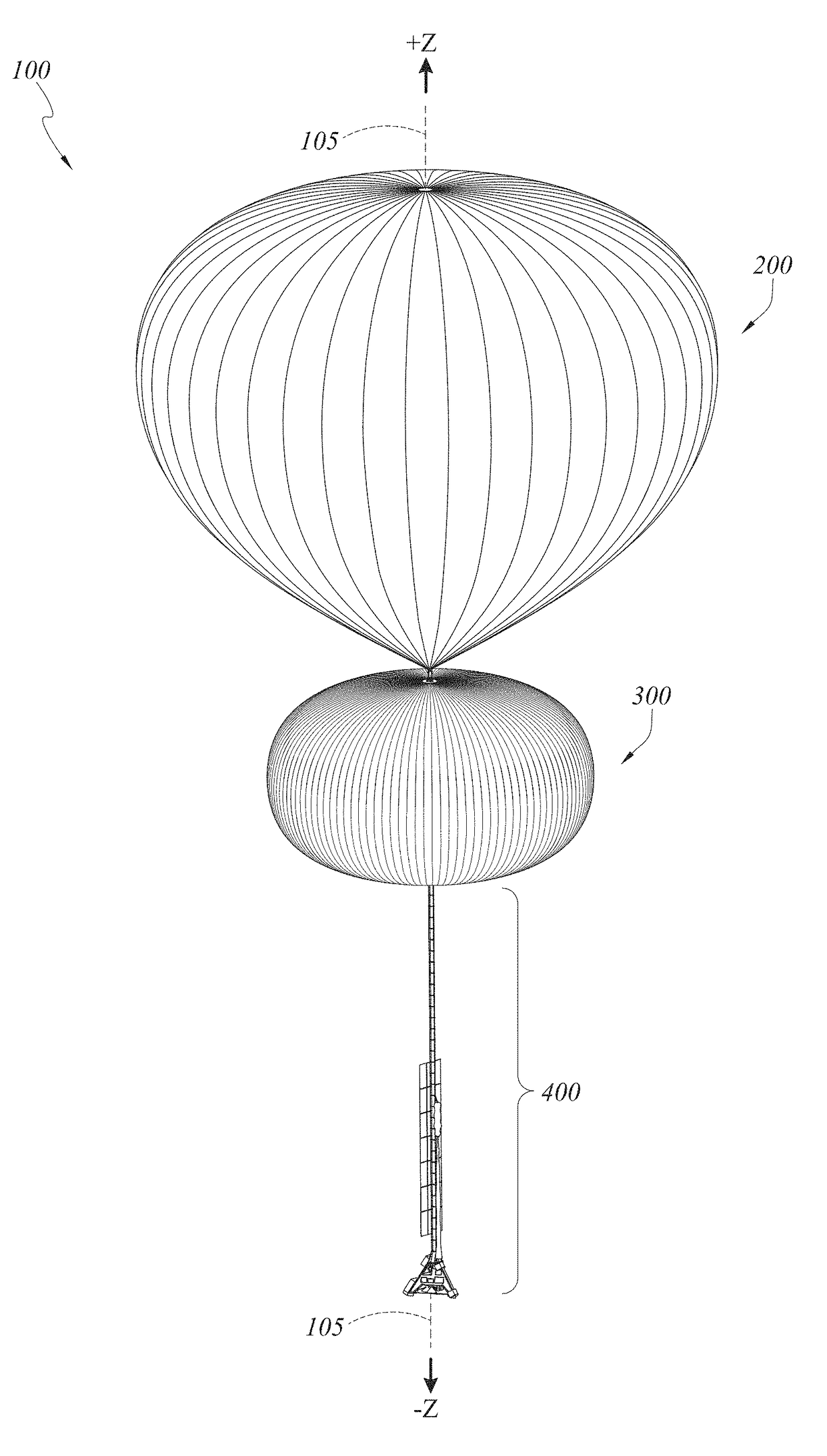
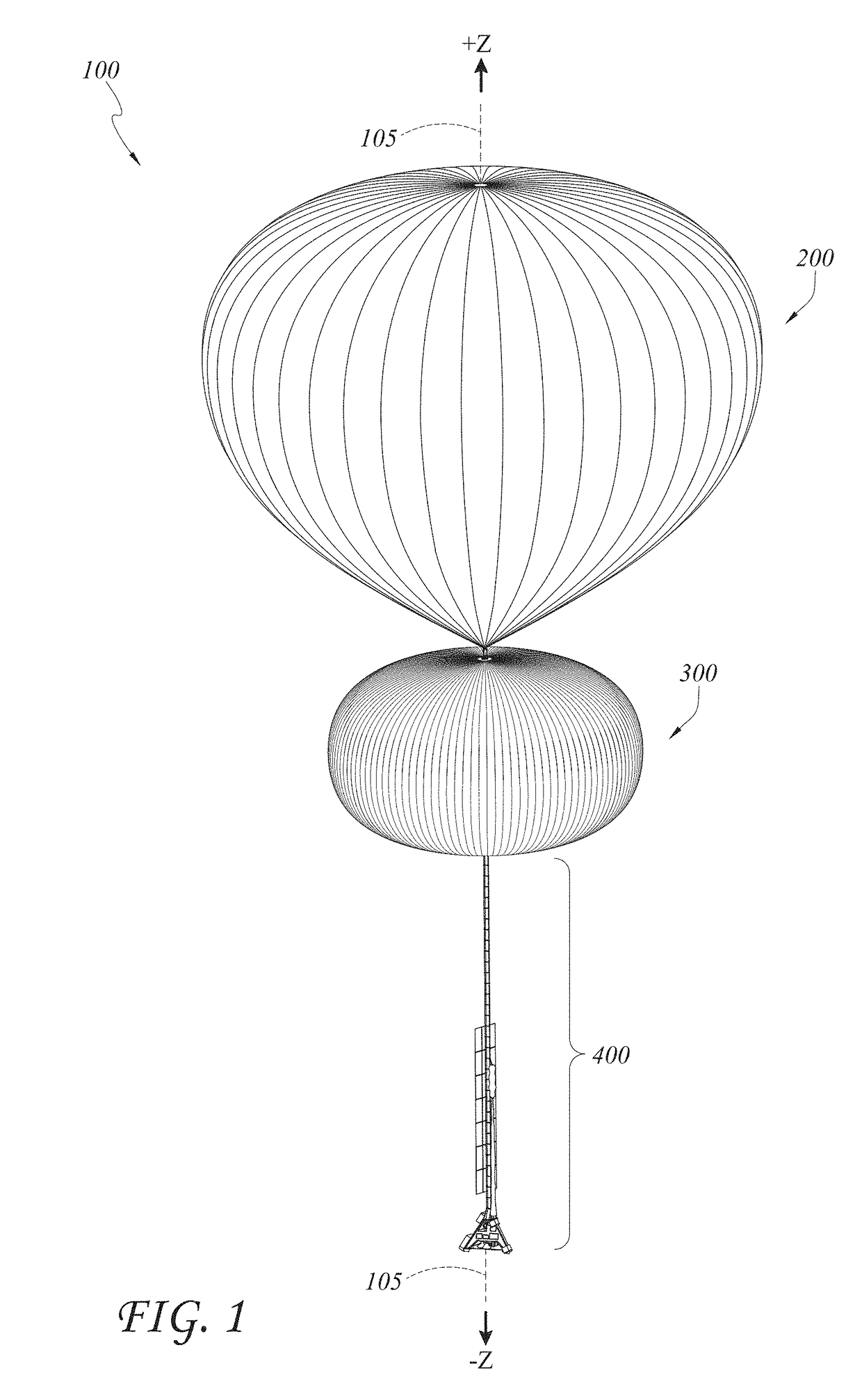
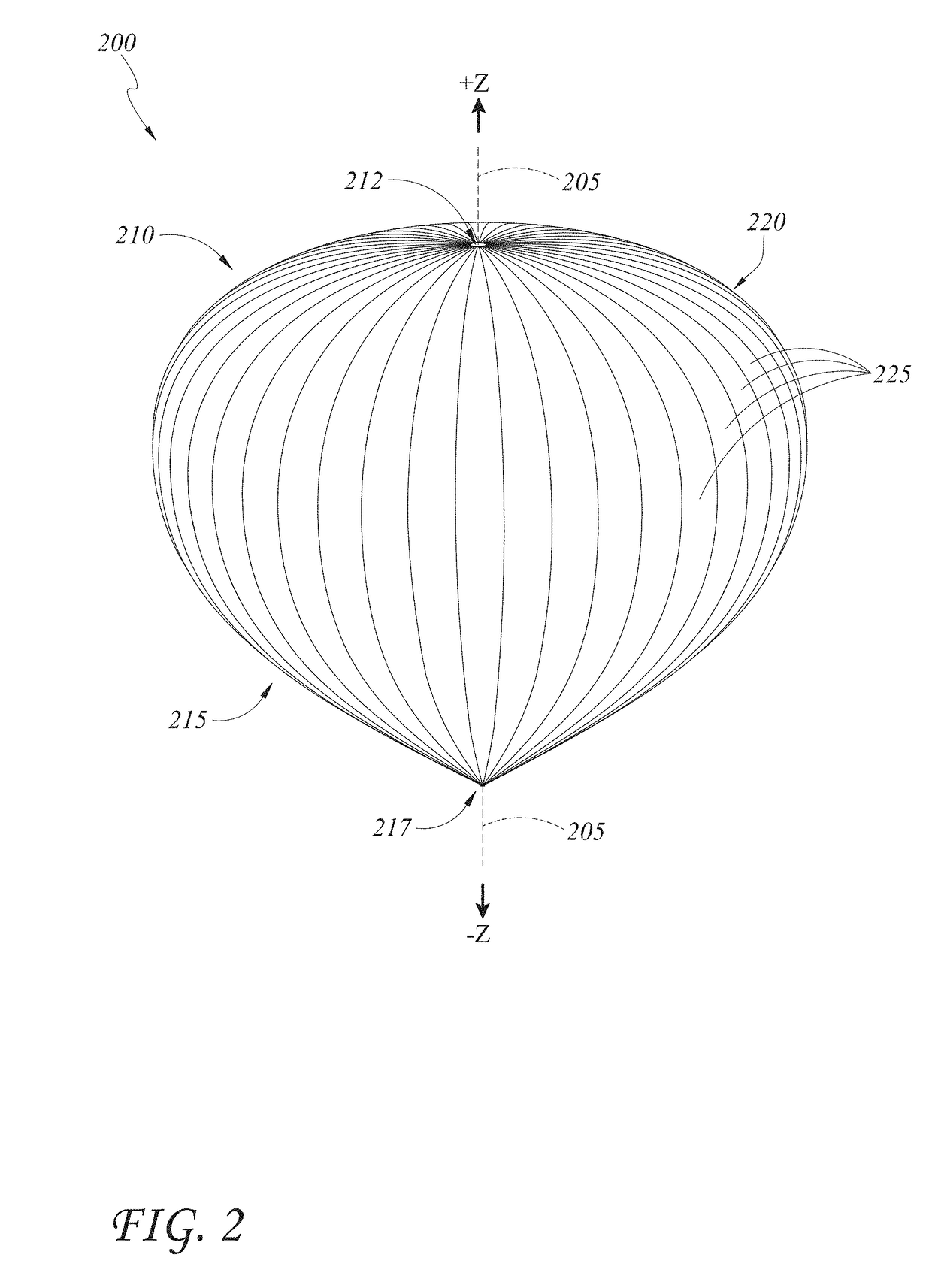
[0007]Described herein are riser release systems and devices for descending and landing flight vehicles, such as parafoils. The flight vehicles may land from any altitude, including but not limited to landing from high altitude flight (generally above 50,000 feet), for example using lighter-than-air (LTA) systems. Therefore, as examples only, some LTA systems and methods are thus described, and it is understood that the riser release systems and methods described ...


PUM


Abstract

Described herein are features for a riser release flaring system for parafoils and other descent flight vehicles for controlled descent and landing of the flight vehicle. The descent flight vehicle may have a payload suspended by a canopy. The descent flight vehicle may be released from a high altitude lighter-than-air (LTA) system, from another system, or may not be associated with any other flight system. The riser release auto flare system is used with the descent system, such as the parafoil, for controlled and safe landing of the payload. Riser lines are released at a controlled rate and for a fixed distance to automatically cause the payload to pull control lines to flare the parafoil and slow a descent and/or forward speed of the vehicle. The riser lines may be released in response to the descent system satisfying a landing criterion, such as altitude.

Description

INCORPORATION BY REFERENCE TO ANY RELATED APPLICATIONS[0001]Any and all applications for which a foreign or domestic priority claim is identified in the Application Data Sheet as filed with the present application are hereby incorporated by reference in their entirety under 37 CFR 1.57.[0002]This application claims the benefit of priority to U.S. provisional patent application No. 62 / 322,150, entitled RISER RELEASE FLARING SYSTEM FOR PARAFOILS, and filed Apr. 13, 2016, the disclosure of which is hereby incorporated by reference herein in its entirety for all purposes and forms a part of this specification.BACKGROUNDField[0003]The technology relates generally to flight, in particular to systems and methods for descent and landing of flight vehicles.Description of the Related Art[0004]Flight vehicles, such as parafoils and other vehicles, are of interest for many applications, including communications, scientific research, meteorology, reconnaissance, tourism, and others. These and ot...

Claims


Application Information

Patent Timeline
IPC IPC(8): B64D17/62B64D17/02B64B1/04
CPCB64D17/025B64D17/343B64B1/44B64D17/38B64D17/80B64D17/64
Inventor LEIDICH, JAREDMCFATTER, DANIEL W.FELTON, KYLER QUINN
Owner WORLD VIEW ENTERPRISES
Why Eureka
Try Eureka