Splice sleeve with elliptical or compound curve cross section

a sleeve and cross section technology, applied in the direction of rod connection, furniture joining, structural elements, etc., can solve the problems of limited expansion of the grout mass, increase the bonding and strength of the connection, etc., to achieve maximum bonding and shear resistance, increase the splicing capacity of the overlapping, and simple construction

Inactive Publication Date: 2014-01-23
AE CONNECTOR SOLUTIONS
View PDF5 Cites 5 Cited by
  • Summary
  • Abstract
  • Description
  • Claims
  • Application Information

AI Technical Summary

Benefits of technology

[0007]The splice sleeve of the present invention has an elliptical cross section or one constructed in the form of compound curves and is configured to receive and accommodate the overlapped ends of the reinforcing bars along the radial axis having the greatest dimension. When the rebar ends are in place in the splice sleeve, the sleeve is then filled with hardenable material to resist axial tension or compression exerted on the reinforcing bars. The action of the sleeve is to hold the hardenable material in tight confinement against the surfaces of the overlapping reinforcing bar ends so that the surface deformation ridges of these bars will provide a tight gripping action with the confined hardenable material.
[0008]The hardenable material may contain an expansion agent which results in limited expansion of the grout mass that is firmly confined in the interior area of the tube sleeve. The inclusion of an expansion agent can induce tremendous internal pressures on the lapped ends of the rebars which greatly increases the bonding and strength of the connection.
[0009]The splice sleeve of the present invention is preferably provided with an inwardly directed lip at one or both ends. The lip reduces the inner diameter of the sleeve at the ends to provide added restraint against longitudinal shifting of the internal grout mass and therefore maximizing the confinement of the overlapping ends of the connected rebars. Another purpose of these lips is to serve as a guide to position the rebars to allow a gap of at least 3 mm between the outer rebar surface and the interior surface of the splice sleeve tube thus allowing the liquid hardenable grout to fill the gap and provide the necessary peripheral grout mass for confinement and frictional resistance of the rebars.
[0010]Accordingly, an object of the present invention is to provide a splice sleeve for interconnecting reinforcing bars in the form of a rigid sleeve having an elliptical or compound curve cross section in which the overlapping ends of the reinforcing bars are positioned in the sleeve. The space between the reinforcing bar ends and between the bars and the sleeve is filled with hardenable cementitious material such as grouting or the like so that the sleeve will restrain any radial displacement of the cementitious material thereby developing a confinement of the cementitious material and preventing it from outward movement thereby resulting in substantial “lock” between the surface deformation ridges of the rebars to provide significant resistance to axial tension and / or compression failure or displacement of the overlapped reinforcing bar ends.
[0012]A further object of the present invention is to provide a splice sleeve with an elliptical or compound curve cross section for overlapping reinforcing bars as set forth in the preceding objects in which one or both ends of the sleeve include an inwardly directed lip that provides added restraint against shifting of the internal grout mass and increases the splicing capacity of the overlapping sleeve arrangement as compared with cylindrical sleeve configurations. The inwardly directed lip at the ends of the sleeve also serves to position the rebar in a way to form a minimum gap of 3 mm between the rebar and the interior surface of the sleeve to ensure that a minimum thickness of the internal grout mass can be effectively formed completely around the perimeter of the rebar ends for the development of maximum bonding and shear resistance when restrained by the inwardly directed lip at each end of the sleeve.
[0013]A still further object of the present invention is to provide an elliptical or compound curve cross section splice sleeve for overlapping reinforcing bars which is simple in construction, easy to assemble and effective for securely restraining the overlapped ends of the reinforcing bars in connected relation in order to resist axial tension and / or compression exerted on the reinforcing bars.

Problems solved by technology

The hardenable material may contain an expansion agent which results in limited expansion of the grout mass that is firmly confined in the interior area of the tube sleeve.
The inclusion of an expansion agent can induce tremendous internal pressures on the lapped ends of the rebars which greatly increases the bonding and strength of the connection.

Method used


Image

  • Splice sleeve with elliptical or compound curve cross section
  • Splice sleeve with elliptical or compound curve cross section
  • Splice sleeve with elliptical or compound curve cross section

Examples


Embodiment Construction

[0026]In describing preferred embodiments of the invention illustrated in the drawings, specific terminology will be resorted to for the sake of clarity. However, the invention is not intended to be limited to the specific terms so selected, and it is to be understood that each specific term includes all technical equivalents which operate in a similar manner to accomplish a similar purpose.

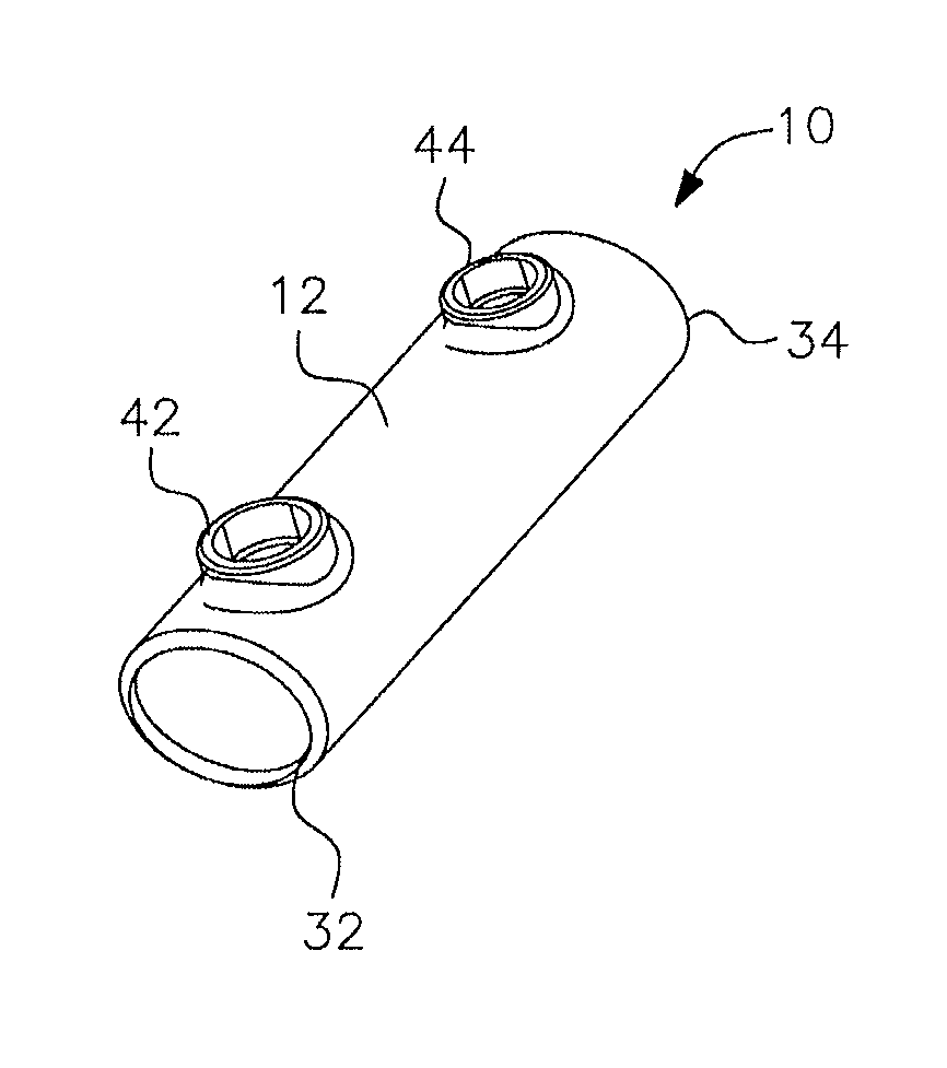
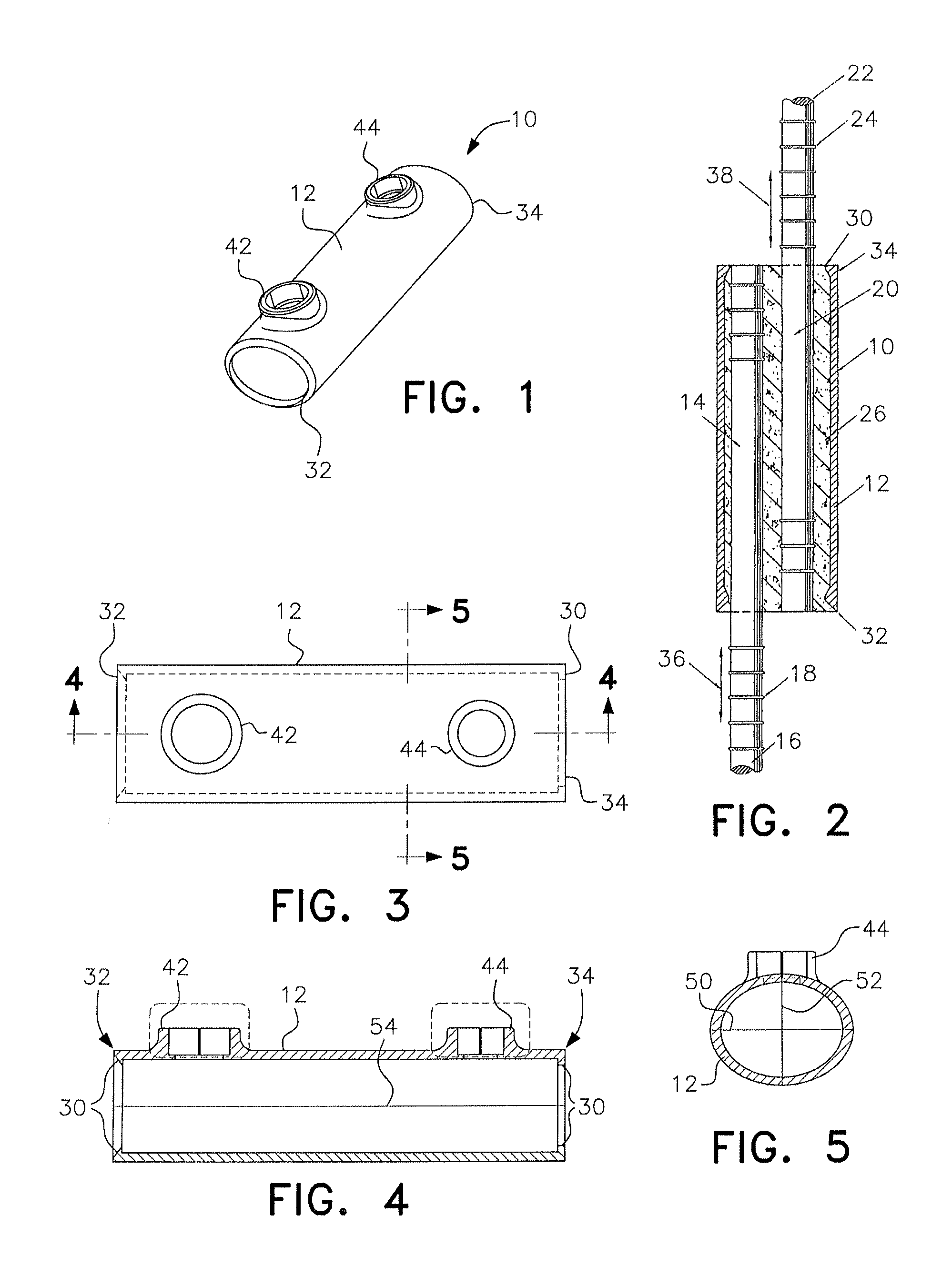
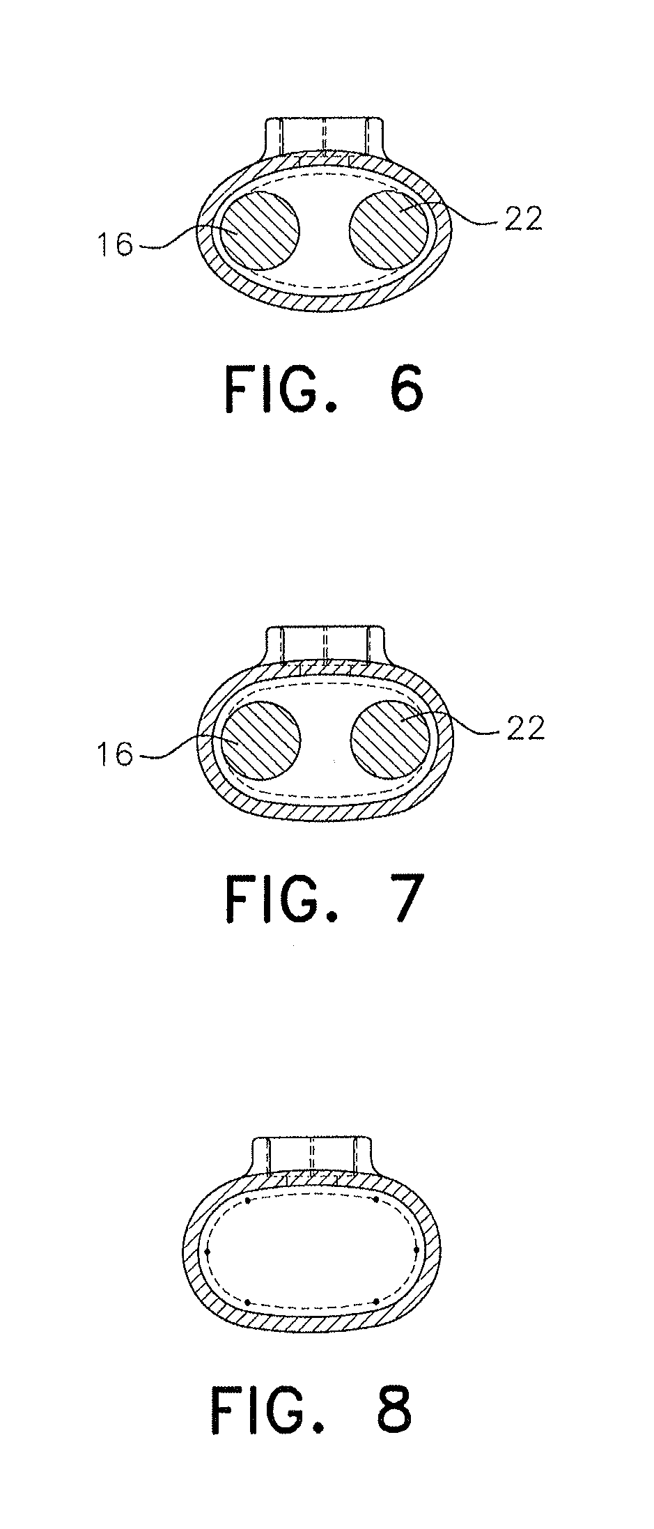
[0027]Referring now specifically to the drawings and FIG. 1 in particular, the splice sleeve of the present invention is generally designated by numeral 10 and includes a short section of rigid steel tubing or pipe forming a sleeve 12 of elliptical cross section configuration. When the sleeve is vertically oriented in use, as shown in FIG. 2, the sleeve 12 receives the upper end portion 14 of a lower reinforcing bar 16 having longitudinally spaced peripheral ribs or projections 18 thereon. The sleeve 12 also receives the lower end portion 20 of an upper reinforcing bar 22 which also has longitudi...


PUM

PropertyMeasurementUnit
thicknessaaaaaaaaaa
diameteraaaaaaaaaa
diameteraaaaaaaaaa

Abstract

A splice sleeve having an elliptical or compound curve cross section for connecting overlapping end portions of reinforcing bars utilized in various types of structures in which steel reinforcing bars are utilized and it is desired to connect the overlapping end portions of the reinforcing bars. The splice sleeve is configured to receive the overlapped end portions of the reinforcing bars and then be filled with hardenable material to resist axial tension and compression exerted on the reinforcing bars. In one embodiment, both ends of the sleeve are provided with an inwardly directed lip to increase the splicing capacity of the sleeve and also to serve as a guide to position the rebars to a minimum of about 3 mm from the inside wall surface of the sleeve.

Description

RELATED APPLICATION[0001]This is a continuation of U.S. application Ser. No. 13 / 191,922 filed on Jul. 27, 2011, the disclosure of which is hereby incorporated by reference in its entirety.BACKGROUND OF THE INVENTION[0002]1. Field of the Invention[0003]The present invention generally relates to a splice sleeve tube device for joining the ends of at least two reinforcing bars utilized in various types of structures in which steel reinforcing bars are utilized, and it is desired to interconnect the overlapping end portions of such reinforcing bars. The splice sleeve tube device has an elliptical cross section or a curved cross section composed of curvatures of varying radii, referred to herein as a compound curve cross section, to receive and accommodate the end portions of the reinforcing bars in an overlapping relationship, with the splice sleeve being filled with hardenable material to resist axial tension or compression exerted on the reinforcing bars.[0004]2. Description of the Re...

Claims


Application Information

Patent Timeline
Patent Type & Authority Applications(United States)
IPC IPC(8): E04B1/41
CPCE04B1/41Y10T403/477Y10T29/4998E04C5/165E04B1/388F16B7/0433
Inventor YEE, ALFRED A.
Owner AE CONNECTOR SOLUTIONS
Why Eureka
Try Eureka