Through-air dryer assembly

a technology of through-air dryers and dryers, which is applied in the direction of dryers, drying machines with progressive movements, lighting and heating apparatus, etc., can solve the problems of increasing equipment cost, requiring a substantial amount of labor intensive and critical welding, and being difficult to ship. , to achieve the effect of reducing the structural demands of the device, facilitating shipping, and simple calculation of loads

Inactive Publication Date: 2005-06-30
KIMBERLY-CLARK WORLDWIDE INC
View PDF44 Cites 20 Cited by
  • Summary
  • Abstract
  • Description
  • Claims
  • Application Information

AI Technical Summary

Benefits of technology

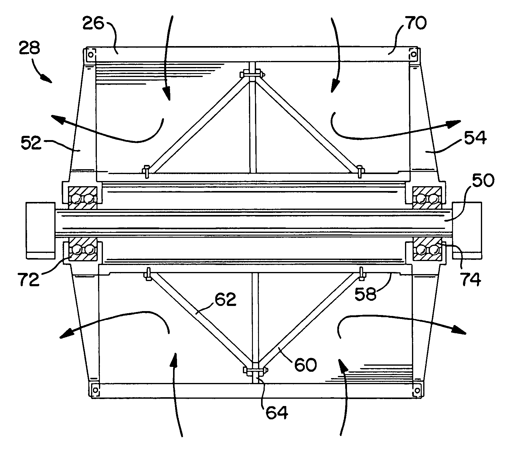
[0008] In general, the present invention is directed to an apparatus for through-air drying webs. The through-air dryer of the present invention is capable of being disassembled and is therefore easy to ship. The through-air dryer is also capable of accommodating all different sizes, and may, for instance, be built to have large diameters. Further, the through-air dryer is configured so that no significant moments are present in the head or shell from outboard placement of bearings and supports, thereby lessening the structural demands of the device. The use of simple plates to form the deck makes it relatively simple to calculate loads that are exerted on the dryer.
[0010] The support structure, for example, may comprise a first hub spaced from a second hub. Each hub engages an opposite end of the cylindrical deck. A first bearing is positioned between the first hub and the support shaft and a second bearing is positioned between the second hub and the support shaft. Each bearing is placed substantially in alignment with each end of the cylindrical deck in order to prevent the creation of moment from the offset of the location of the load relative to the location of support. The alignment of the bearing in the support structure eliminates the moment that the deck is required to carry so that the deck can be designed for fabric load, rotational acceleration and pressure differential alone.
[0015] For gas flow into the dryer it is advantageous to limit the width of the deck plate as it contacts the web to reduce the tendency to cause sheet marking. It has been found that a contact width of less than 3 mm (1 / 8 inches) is preferable to prevent sheet marking. This thickness is dependent on the thickness of the fabric. For example, thicker more three dimensional fabrics allow flow in the machine direction so marking would be less noticeable. The location of internal supports is also ideally located away from direct contact with the fabric to facilitate air flow.
[0017] In accordance with the present invention, the cylindrical deck and the support structure may be made from multiple parts that may be easily assembled. For instance, as described above, the cylindrical deck is made from a plurality of plates. In addition, the support structure may include opposing hubs that also may be comprised of multiple parts. In this manner, when the apparatus is being shipped, the shipping volume of the apparatus may have a greatest dimension of no greater than one half the diameter of the cylindrical deck.

Problems solved by technology

Through-air dryers, however, are typically much more expensive to manufacture and ship in comparison to other drying devices.
In the past, the decks have been made from expensive materials, such as stainless steel, and have been manufactured using expensive procedures.
For instance, in order to make the decks porous, the decks are typically configured to have a honeycomb-like structure that requires a substantial amount of labor intensive and critical welding.
In order to support the cylindrical deck and to control air flow through the deck, many through-air dryers also include internal baffles and seals that further increase the cost of the equipment.
Further, since the cylindrical deck is a one-piece construction, the shipping costs for through-air dryers are exorbitant.
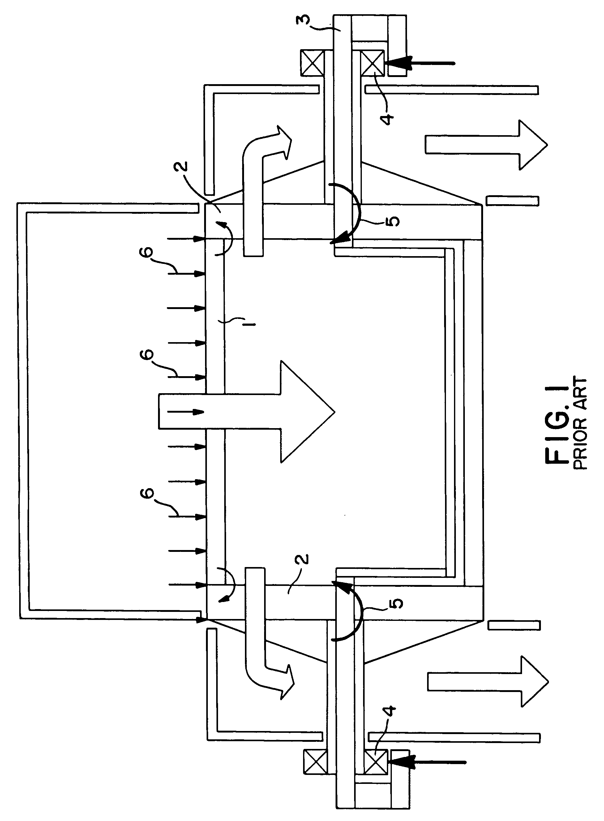
Unfortunately, as a result of the placement of the bearings 4, moments represented by the arrows 5 are created when a load 6 is placed on the through-air dryer during operation.
Thus, due to the presence of the moments, even greater deck thicknesses and massive heads are required in designing the through-air dryer, further increasing the cost to manufacture the dryer and the cost to ship the dryer.
An added problem with the existing design is that significant stresses are caused by the differential expansion of components during the heating of the through-air dryer and by the differential temperatures of the through-air dryer during steady-state operation.
This subjects the dryer to lowest differential loads, but there are always stresses induced with a rigid design.
While this helps to alleviate the problem, the cost of the through-air dryer is much higher because of the expense of special materials and the special machining and handling necessary to weld them.

Method used


Image

  • Through-air dryer assembly
  • Through-air dryer assembly
  • Through-air dryer assembly

Examples


example 1

[0060] One feature of the through-air dryer (“TAD”) design of the present invention is the ability to rapidly calculate loads and deflections analytically using well-established mechanical engineering principles. The purpose of this example is to show analytical methods that may be used to calculate the deflections and loads on support bars for a TAD manufactured using the principles of this invention.

[0061] The TAD dryer deck is formed from a multiplicity of individual plates defining a cylinder. Each deck plate comprises a simply supported section bar as shown in FIG. 7.

[0062] The bar has an axial length (l), a radial width (w) and a thickness (t). For the purposes of this example the thickness and width is fixed as constant. Designs can be adjusted to vary both thickness and width to optimize the use of materials and enhance the process. For example the width can be varied to be larger at the locations of highest stress, generally in the center of an unsupported span. Likewise ...

example 2

[0098] The following is a prophetic example using the equations derived in Example 1. Typical dimensions of a through-air dryer (“TAD”) were used. A typical TAD for the manufacture of tissue paper products is about 5 m (16.4 feet) in diameter, has a width of 5.2 m (17.1 feet). A typical maximum operating speed is 1500 m / min (4921 ft / min) at the surface of the deck. Maximum deflection of 3 millimeters (⅛ inch) is allowed although less is preferable to prevent premature wear or wrinkling of the fabric. For the case of this example, the bars are rectangular in shape although there are advantages to reducing the thickness of the bar at the periphery of the TAD where the bars contact the fabric to prevent non-uniform air flow as previously discussed.

[0099] Also, a rectangular bar is not the optimum shape for maximizing the rectangular moment of inertia relative to the weight. A manufactured material consisting of a tube with wearing surfaces would provide more rigidity especially to pre...


PUM


Abstract

A through-air dryer is disclosed. The through-air dryer includes a cylindrical deck made from a plurality of deck plates that support a throughdrying fabric. The deck plates are supported by opposing hubs. Each of the hubs is in communication with a bearing that is mounted to a stationary shaft for allowing the cylindrical deck and the hubs to rotate. The bearings are positioned so as to create a through-air dryer structure that remains stable during operation and allows for easy calculation of loads on the dryer.

Description

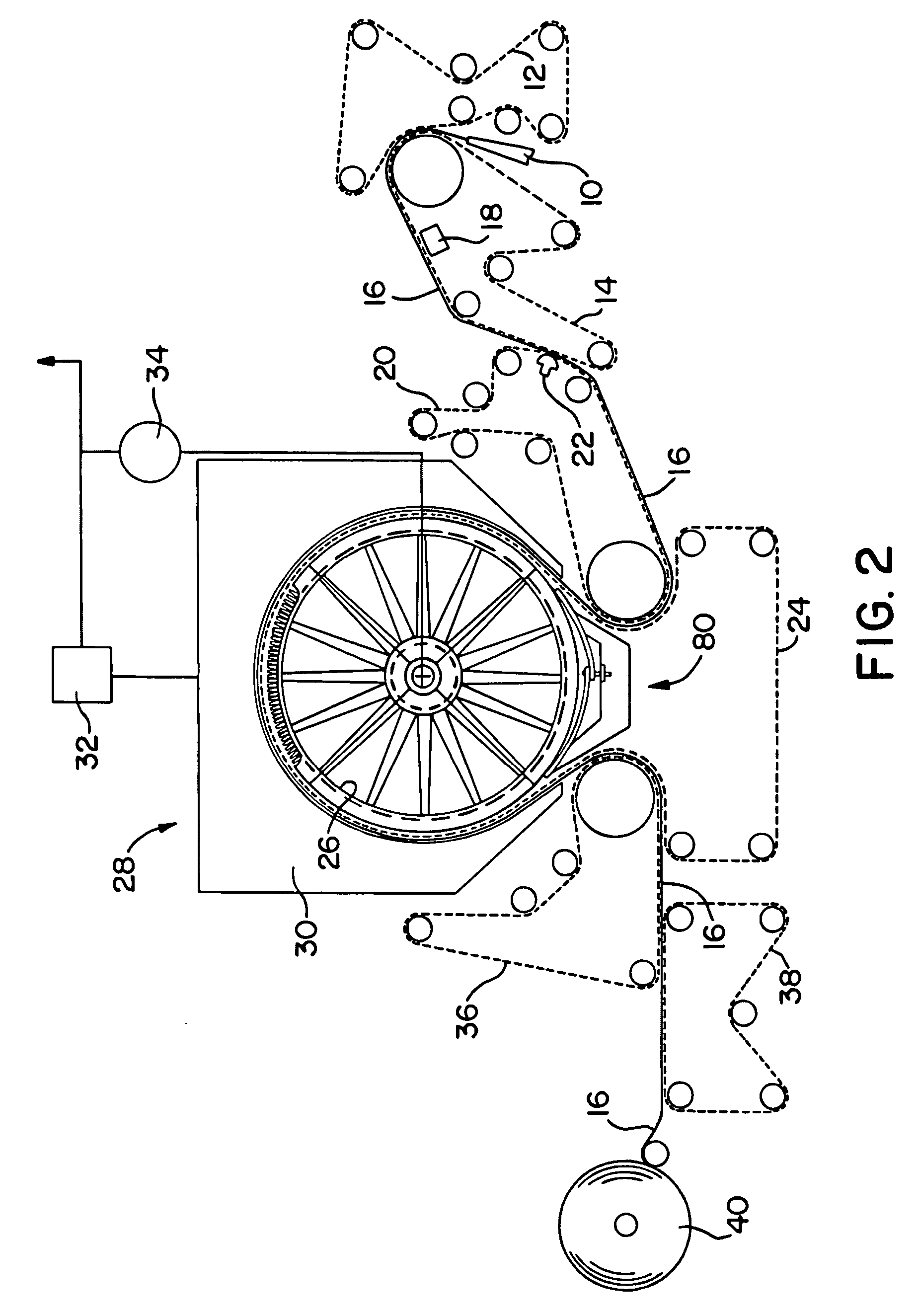
BACKGROUND OF THE INVENTION [0001] In the manufacture of high-bulk tissue products, such as facial tissue, bath tissue, paper towels, and the like, it is common to use one or more through-air dryers for partially drying the web or to bring the tissue web to a final dryness or near-final dryness. Generally speaking, through-air dryers typically include a rotating cylinder having an upper deck that supports a drying fabric which, in turn, supports the web being dried. In particular, heated air is passed through the web in order to dry the web. For example, in one embodiment, heated air is provided by a hood above the drying cylinder. Alternatively, heated air is provided to a center area of the drying cylinder and passed through to the hood. [0002] When incorporated into a papermaking system, through-air dryers offer many and various benefits and advantages. For example, through-air dryers are capable of drying tissue webs without compressing the web. Thus, moisture is removed from th...

Claims


Application Information

Patent Timeline
Patent Type & Authority Applications(United States)
IPC IPC(8): D21F5/18
CPCD21F5/182F26B13/16F26B13/101D21F5/184
Inventor HADA, FRANK S.HERMANS, MICHAEL A.GROPP, RONALD F.COSTELLO, PETER K.
Owner KIMBERLY-CLARK WORLDWIDE INC
Why Eureka
Try Eureka