Composite Doctor Arrangement

a doctor arrangement and doctor technology, applied in the field of compact doctor arrangement, can solve the problems of large installation space, deflecting clearly, large weight, etc., and achieve the effect of improving the versatility of application and being easy and simple to fasten

Inactive Publication Date: 2006-12-28
VALMET TECH INC
View PDF10 Cites 21 Cited by
  • Summary
  • Abstract
  • Description
  • Claims
  • Application Information

AI Technical Summary

Benefits of technology

[0007] An objective of the present invention is to accomplish a new type of composite doctor arrangement which is more versatile than before and to which it is easy and simple to fasten various types of blade holders without extra limitations or tension. The characteristic features of the present invention will be more fully understood from the following description and drawings. In the doctor arrangement of the present invention, a rigid construction is achieved by the suitable dimensions and design of the parts without problems caused by thermal expansion. In other words, materials suitable for each purpose can be used in the manufacture of the parts, and the parts can be given the optimum dimensions. Moreover, existing parts can be used in the doctor arrangement without problems. Furthermore, the design can be used for improving the versatility of application, which adds to the variations of the doctor arrangement even almost without additional costs.

Problems solved by technology

When the beam structures are manufactured conventionally from metal, they become large and heavy.
Hence, they require much installation space, and their own weight alone makes them deflect clearly.
The said beam structures are also sensitive to vibration, which complicates the operation of the doctor arrangement.
However, the composite construction calls for the use of expensive raw materials.
Furthermore, it is problematic to join other parts included in the doctor arrangement to the beam structure.
Moreover, the mounting piece becomes large, which increases the manufacturing costs and complicates the placement of the mounting piece in the doctor arrangement.
Further problems are caused by the fastening of commercially available blade holders to the composite mounting piece by means of screws.
This causes torsion and tension between the parts primarily due to differences in their thermal expansion coefficients.
In other words, the manufacture of the doctor arrangement involves several limitations and problems, which add to the manufacturing costs and complicate the use of the doctor arrangement.

Method used


Image

  • Composite Doctor Arrangement
  • Composite Doctor Arrangement
  • Composite Doctor Arrangement

Examples


Embodiment Construction

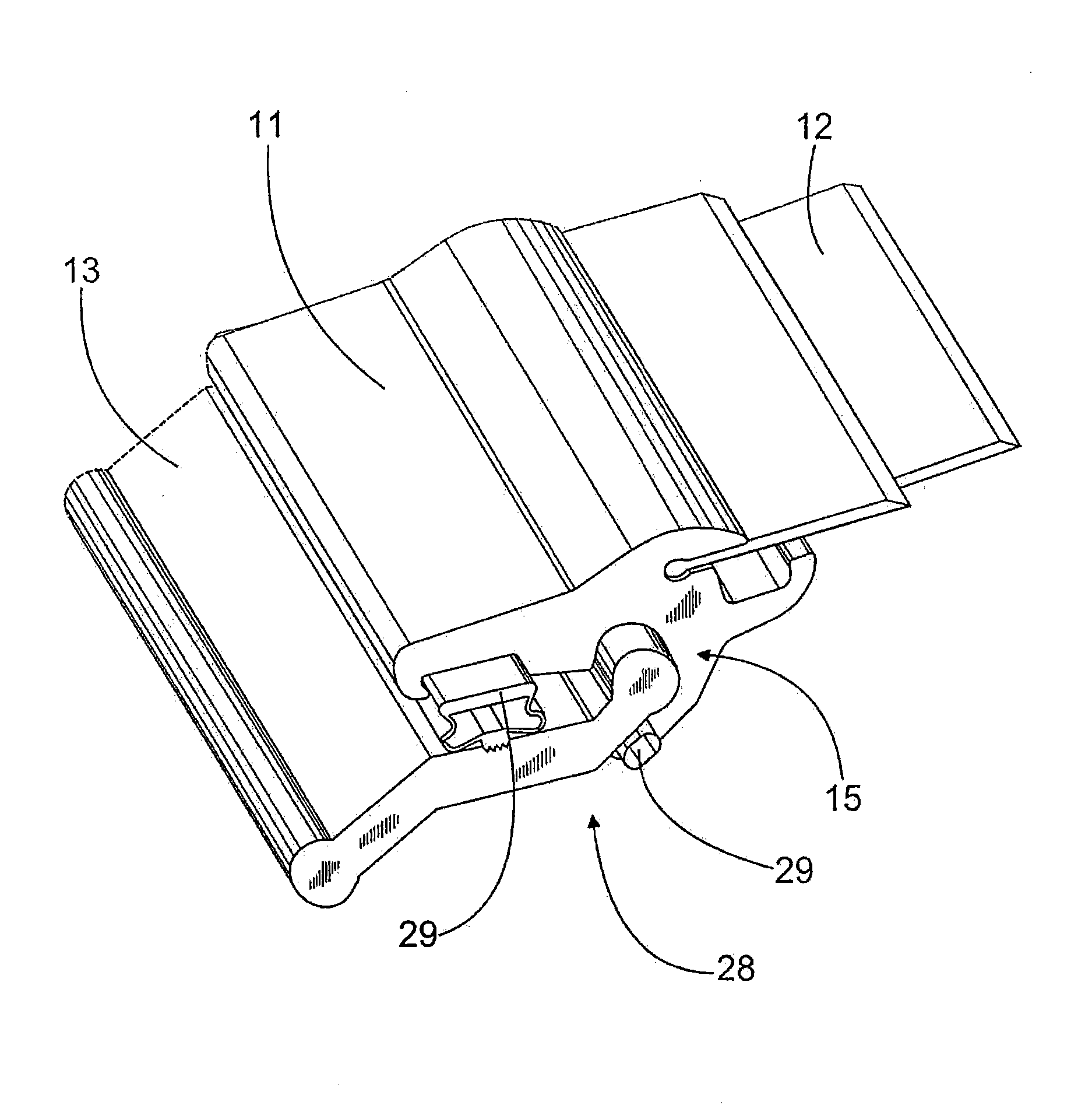
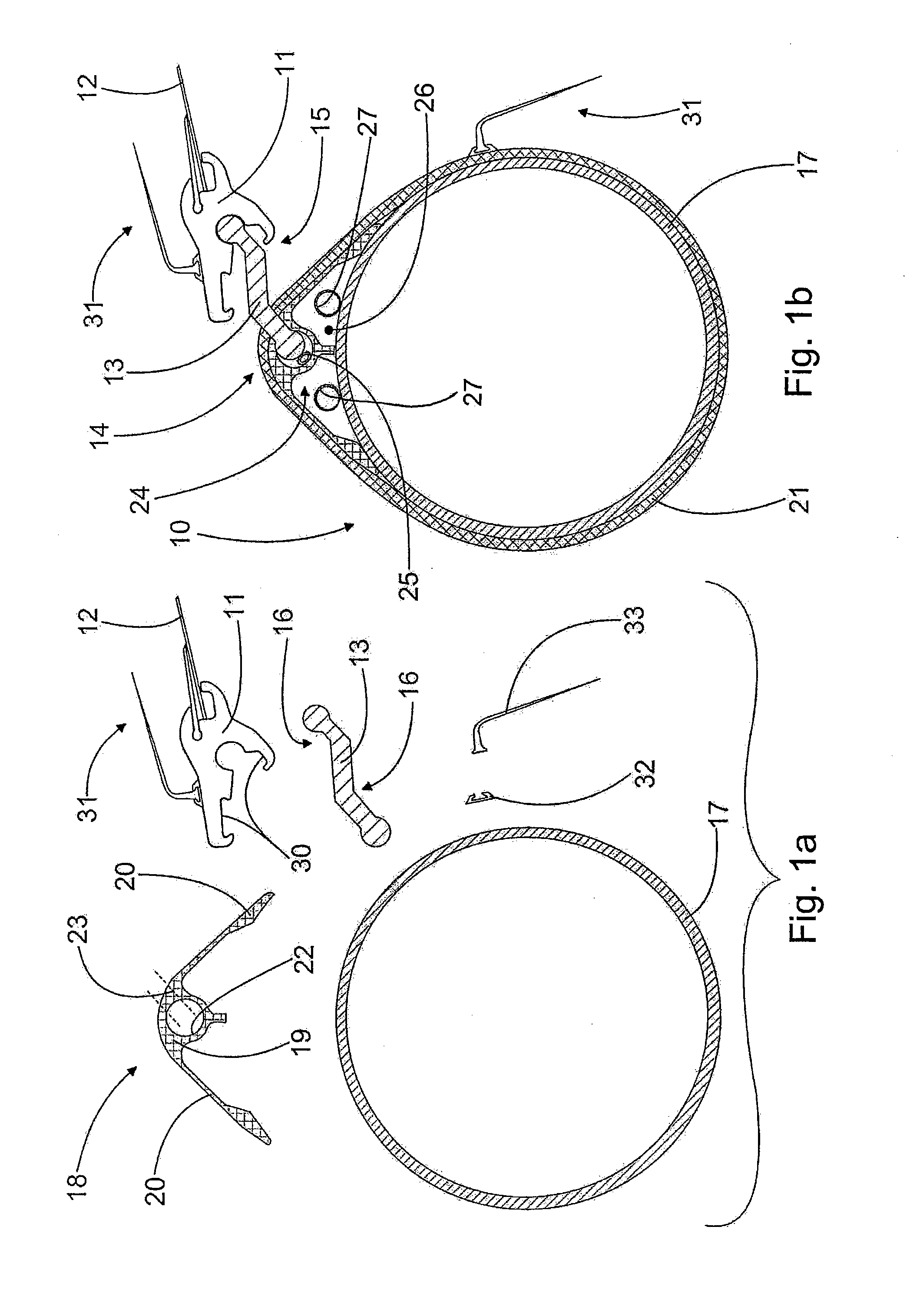
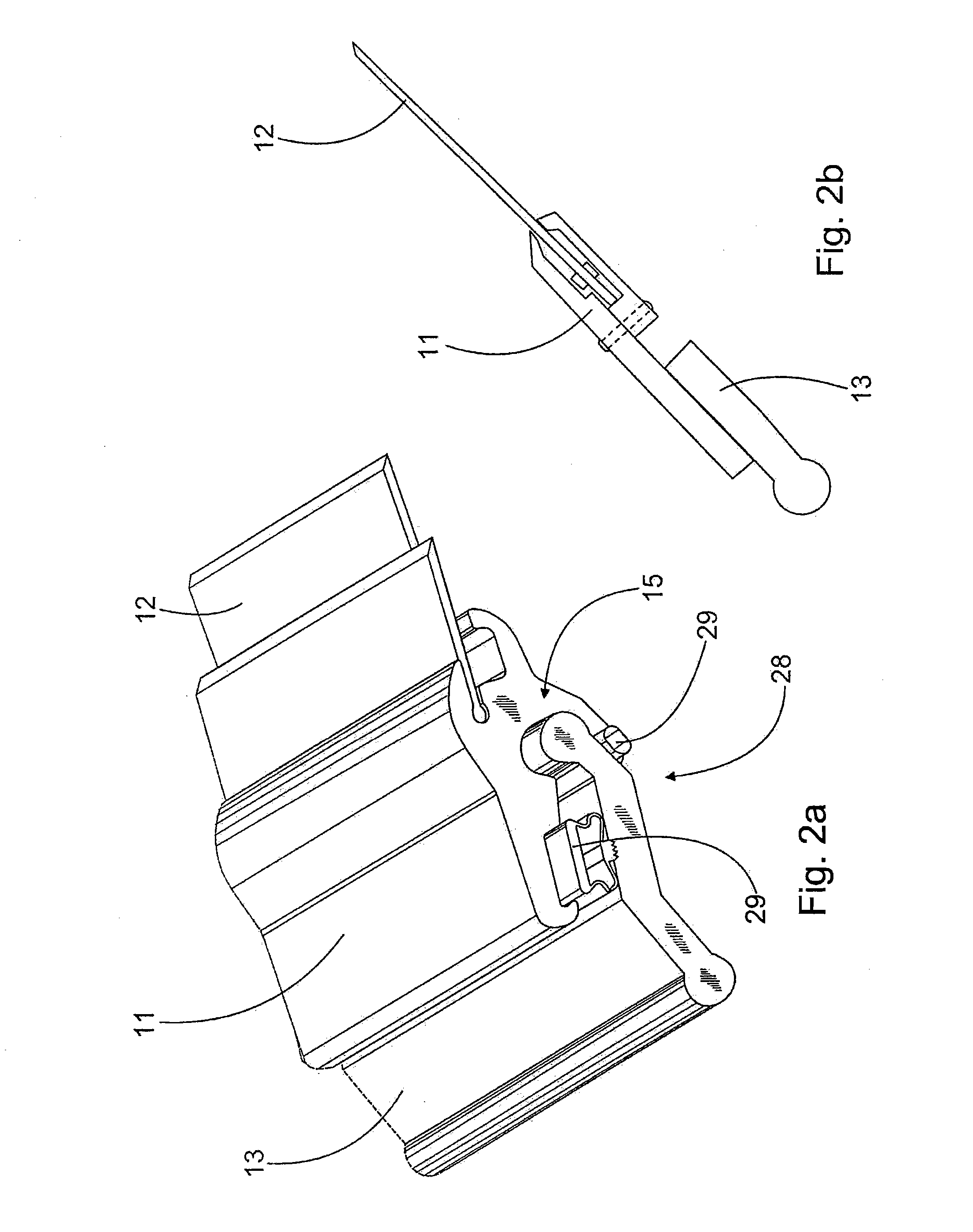
[0014]FIGS. 1a and 1b illustrate one example of the doctor arrangement according to the invention and of its manufacture. The doctor arrangement is especially intended for use in conjunction with a web forming machine. In this case, the beam structure 10 included in the doctor arrangement is typically several meters long, presently up to more than 10 meters long. Moreover, the doctor arrangement comprises the blade holder 11, to which the blade 12 of the doctor arrangement is fastened. The same reference numbers have been used of parts with similar functions. The blade 12 doctors a moving surface, for example the surface of a revolving roll as shown in FIG. 3. The beam structure 10 also comprises the mounting piece 13 for the blade holder 11. According to the invention, the mounting piece 13 is fitted movably in axial direction in the beam structure 10 by means of a form-locked mounting counterpiece 14. This avoids the use of glue and screw connections, which have caused problems ea...


PUM

PropertyMeasurementUnit
lengthsaaaaaaaaaa
plate-like shapeaaaaaaaaaa
beam structureaaaaaaaaaa

Abstract

A composite doctor arrangement for a web forming machine or web handling machine has a beam structure (10) with a mounting piece (13) fitted to it. A blade holder (11) is fitted to the mounting piece, with a blade (12) fitted to the blade holder (11). The mounting piece (13) is fitted axially and movably in the beam structure (10) by a form-locked mounting counterpiece (14), where the form locking is arranged so that it is fixed in the lateral direction of the blade (12) and essentially free in the longitudinal direction of the blade (12).

Description

CROSS REFERENCES TO RELATED APPLICATIONS [0001] This application claims priority on Finnish Application No. FI 20055321, filed Jun. 17, 2005, the disclosure of which is incorporated by reference herein. STATEMENT AS TO RIGHTS TO INVENTIONS MADE UNDER FEDERALLY SPONSORED RESEARCH AND DEVELOPMENT [0002] Not applicable. BACKGROUND OF THE INVENTION [0003] The present invention concerns a composite doctor arrangement which is intended for a web forming machine or web handling machine and which has as components a beam structure, a mounting piece fastened to it, and a blade holder fastened to the mounting piece, with a blade included in the doctor arrangement fastened to the blade holder. [0004] Doctor arrangements where the load-bearing element is a beam structure are used in web forming machines, such as in paper, board and tissue machines, and in web handling machines, such as in printing machines. The beam structure is usually supported on the web forming machine only by its ends. Bea...

Claims


Application Information

Patent Timeline
Patent Type & Authority Applications(United States)
IPC IPC(8): D21G3/00B41F9/10D21G
CPCD21G3/005B41F9/1036
Inventor RATA, ILKKAVAARANIEMI, KALLE
Owner VALMET TECH INC
Why Eureka
Try Eureka