
Outwardly deploying airbag system

a technology of airbags and vent holes, which is applied in the direction of tractors, steering devices, cycle equipments, etc., can solve the problems of gas leakage through the vent hole of the airbag, and insufficient impact absorption property

Inactive Publication Date: 2009-07-14
JOYSON SAFETY SYST JAPAN KK
View PDF34 Cites 4 Cited by
  • Summary
  • Abstract
  • Description
  • Claims
  • Application Information

AI Technical Summary

Benefits of technology

"The present invention provides an outwardly deploying airbag system that can maintain the internal pressure of the airbag for a required period without increasing the maximum internal pressure during inflation. The system includes an airbag and a gas generating means that generates gas at multiple times to achieve this. The gas generated during the second step compensates for gas that leaks through a vent means in the airbag, keeping the internal pressure high for a long period. The airbag is inflated in two steps, with the second step performed when the internal pressure falls to a predetermined level after reaching the maximum value. This system can effectively absorb impacts on pedestrians and reduce production costs."

Problems solved by technology

When the internal pressure of an outwardly deploying airbag inflated along the outer surface of the vehicle body is excessively high or excessively low, an impact on the pedestrian or the like cannot be reduced sufficiently.
In this type of airbag, gas does not leak from the vent hole when a pedestrian or the like hits the airbag, and therefore, a sufficient impact absorption property is not necessarily ensured.
When the airbag is provided with a vent hole, gas leaks from the airbag through the vent hole.
In this case, however, the maximum internal pressure of the inflated airbag vainly increases.
Consequently, an impact on the pedestrian or the like cannot be sufficiently reduced, and, for example, the sewing cost and base-cloth cost of the airbag are increased.

Method used


Image

  • Outwardly deploying airbag system
  • Outwardly deploying airbag system
  • Outwardly deploying airbag system

Examples


Embodiment Construction

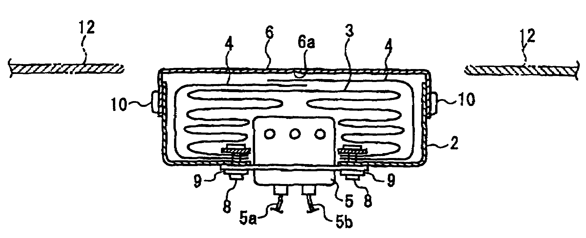
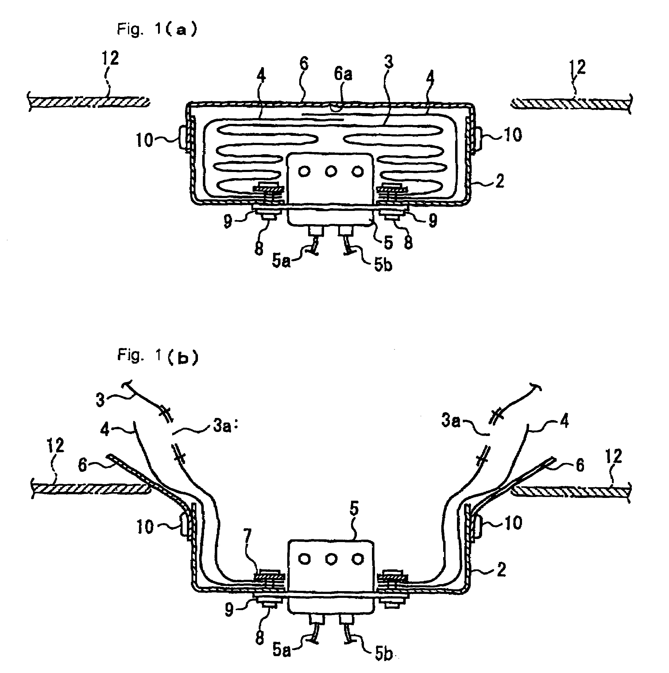
[0018]An embodiment of the present invention will be described below with reference to the drawings. FIGS. 1(a) and 1(b) are cross-sectional views of an outwardly deploying airbag system according to the embodiment, respectively, showing a state before an airbag is inflated and a state after the airbag is inflated.

[0019]An outwardly deploying airbag system 1 includes a container-shaped retainer (airbag holding member) 2 serving as a case having an upper opening, an airbag 3 placed inside the retainer 2 in a folded manner, a protection cloth 4 that covers the folded airbag 3, an inflator 5 for inflating the airbag 3, and a lid (cover member) 6 that covers the upper opening of the retainer 2.

[0020]The inflator 5 is of a multistage type that injects gas in two steps, and two pairs of ignition harnesses 5a and 5b are connected thereto. The airbag 3 has vent holes 3a.

[0021]A tear line 6a formed of a groove is provided on a back surface of the lid 6. In a case in which the airbag 3 is in...


PUM


Abstract

An outwardly deploying airbag system can maintain the internal pressure of an airbag for a required period without vainly increasing the maximum internal pressure of the airbag during inflation. When a sensor detects a collision with a pedestrian, an inflator performs a first gas injection step. An airbag is thereby deployed into a final deployment shape. Subsequently, when the internal pressure of the airbag falls to a predetermined pressure because of leakage of gas through vent holes, and a sensor predicts or detects a collision with a pedestrian, the inflator performs a second gas injection step. Consequently, the internal pressure of the airbag remains high for a long period, and the airbag sufficiently absorbs an impact whenever the pedestrian hits the airbag. The pressure and amount of gas injected in the first gas injection step can be made smaller than in related art, and the required airbag strength is reduced.

Description

FIELD OF THE INVENTION[0001]The present invention relates to an outwardly deploying airbag system that protects a pedestrian, or a passenger of a bicycle or a motorcycle (hereinafter also referred to as a pedestrian or the like) when a vehicle collides with, for example, the pedestrian, the bicycle, or the motorcycle during driving.BACKGROUND OF THE INVENTION[0002]Outwardly deploying airbag systems have been developed as pedestrian-protecting airbag systems that prevent a pedestrian or the like from directly hitting, for example, a wind shield by deploying an airbag along an outer surface of a vehicle body in order to protect the pedestrian or the like when a moving vehicle collides with, for example, the pedestrian, a bicycle, or a motorcycle.[0003]When the internal pressure of an outwardly deploying airbag inflated along the outer surface of the vehicle body is excessively high or excessively low, an impact on the pedestrian or the like cannot be reduced sufficiently.[0004]Japanes...

Claims


Application Information

Patent Timeline
Patent Type & Authority Patents(United States)
IPC IPC(8): B60K28/10B60R21/239B60R21/263B60R21/34B60R21/36
CPCB60R21/36B60R21/239Y02T10/84B60R2021/26058
Inventor TAKIMOTO, TAKAYUKI
Owner JOYSON SAFETY SYST JAPAN KK
Learn More