
Apparatus and method for laser irradiation

a laser irradiation and apparatus technology, applied in the field of apparatus and laser irradiation, can solve the problem of limiting the size of the samples which can be used

Inactive Publication Date: 2010-08-19
LOUGHBOROUGH UNIV
View PDF9 Cites 14 Cited by
  • Summary
  • Abstract
  • Description
  • Claims
  • Application Information

AI Technical Summary

Benefits of technology

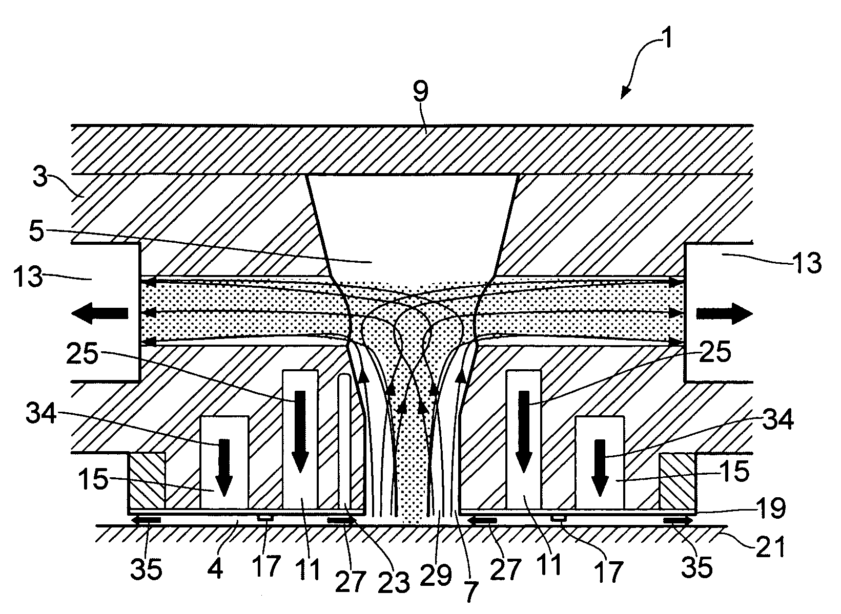
[0007]Embodiments of the invention provide the advantage that the second flow of gas is used to block the ingress of other gases into the first flow of gas and the test volume where the laser irradiation is taking place. This prevents the sample from coming into contact with ambient air or other gases external to the housing so it is not necessary to place the apparatus in a sealed box or to create a vacuum around the apparatus.
[0008]Also the use of a flow controller between the first conduit and the third conduit ensures that the first flow of gas may be independent from the second flow of gas. This enables the amount of gas flow required to control the laser irradiation environment to be reduced.
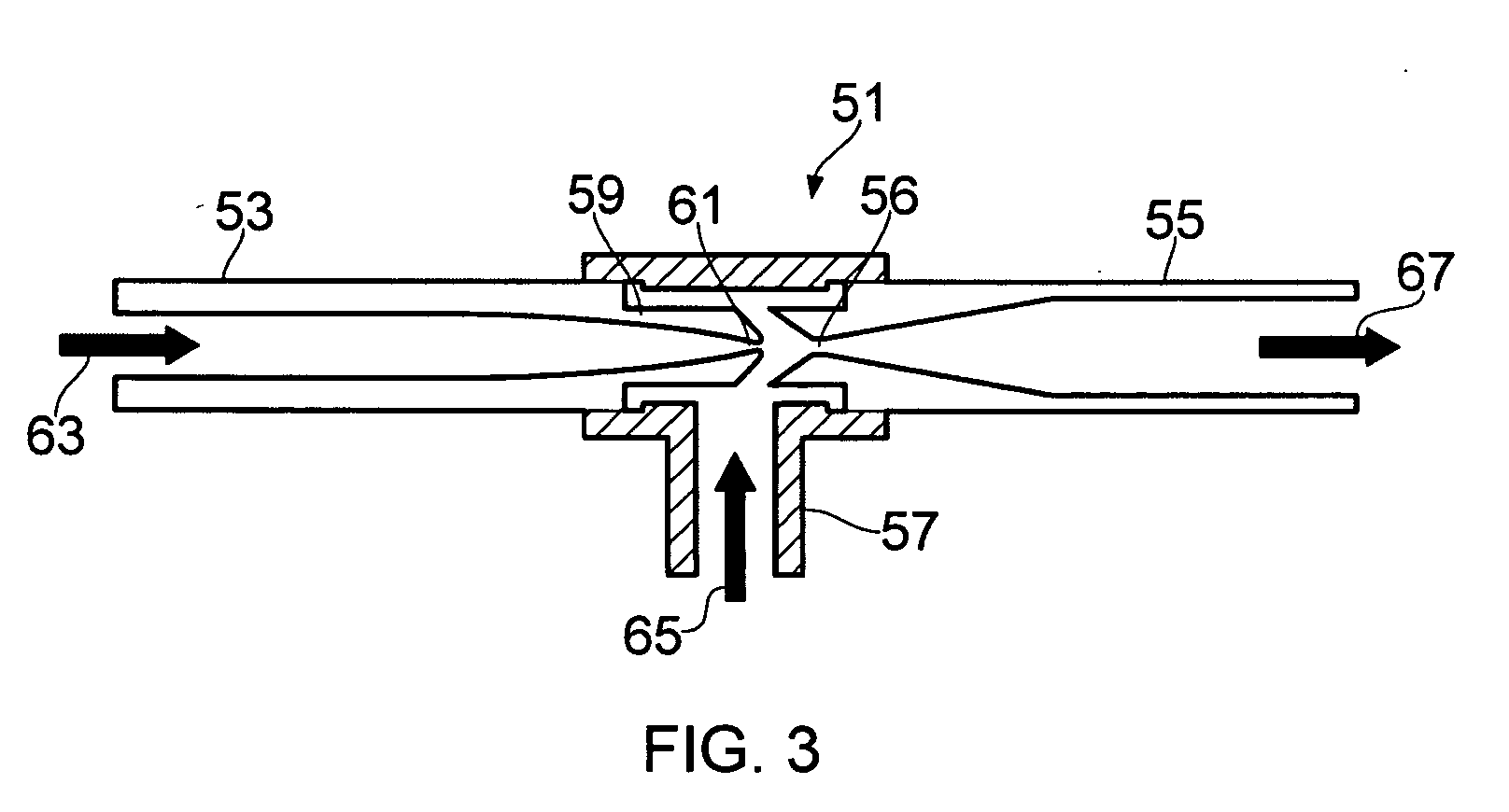
[0011]In some embodiments of the invention a jet pump may be coupled to at least one second conduit. Such embodiments of the invention provide the advantage that the jet pump enables the proportion of gas from the first flow of gas which enters the test volume to be controlled.
[0012]In some embodiments of the invention the first conduit may comprise a grating. In some embodiments of the invention the third conduit may comprise a grating. Such embodiments of the invention reduce the amount of turbulence in the flows of gas.

Problems solved by technology

Known methods of controlling the environment in which laser ablation or MALDI takes place involve placing the sample within a sealed container, however this limits the size of the samples which can be used as they must be able to fit inside the container.

Method used


Image

  • Apparatus and method for laser irradiation
  • Apparatus and method for laser irradiation
  • Apparatus and method for laser irradiation

Examples


Embodiment Construction

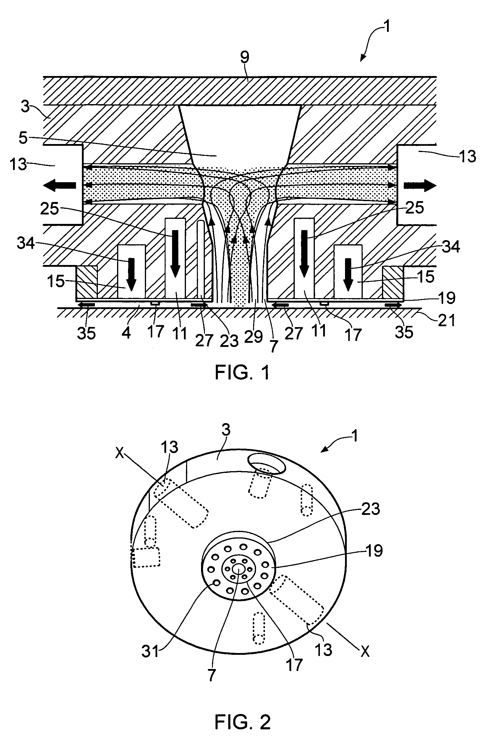
[0006]According to various, but not necessarily all, embodiments of the invention there is provided an apparatus for laser irradiation comprising: a housing wherein the housing defines at least a portion of a test volume; a first conduit configured to provide a first flow of gas into the test volume; a second conduit configured to remove the first flow of gas from the test volume; a third conduit configured to provide a second flow of gas; and a flow controller configured to provide a region of increased flow impedance between the first conduit and the third conduit so that the first flow of gas is directed towards the test volume and the second flow of gas is directed away from the first flow of gas so as to restrict gas external to the housing from coming into contact with the first flow of gas.

[0007]Embodiments of the invention provide the advantage that the second flow of gas is used to block the ingress of other gases into the first flow of gas and the test volume where the las...


PUM

PropertyMeasurementUnit
diameteraaaaaaaaaa
widthaaaaaaaaaa
diameteraaaaaaaaaa

Abstract

An apparatus for laser irradiation including a housing wherein the housing defines at least a portion of a test volume; a first conduit configured to provide a first flow of gas into the test volume; a second conduit configured to remove the first flow of gas from the test volume; a third conduit configured to provide a second flow of gas; and a flow controller configured to provide a region of increased flow impedance between the first conduit and the third conduit so that the first flow of gas is directed towards the test volume and the second flow of gas is directed away from the first flow of gas so as to restrict gas external to the housing from coming into contact with the first flow of gas.

Description

FIELD OF THE INVENTION[0001]Embodiments of the present invention relate to an apparatus and method for laser irradiation. In particular, they relate to an apparatus and method for controlling the environment in which laser irradiation takes place.BACKGROUND TO THE INVENTION[0002]Laser ablation is a method in which a sample is irradiated with a laser beam such that material is removed from the sample. Laser ablation has a wide range of uses in many different areas of technology. For example it may be used to remove material for analysis so that the chemical or structural composition of a sample may be determined. A laser may also be used to cut or drill into a sample or to scribe or etch into the surface of a sample. Laser ablation may also be used to remove any unwanted material from a sample, this may be useful for removing unwanted short circuits in an electrical circuit or for cleaning a sample by removing any impurities from the surface of the sample.[0003]Matrix assisted laser ...

Claims


Application Information

Patent Timeline
Patent Type & Authority Applications(United States)
IPC IPC(8): A61N5/00G21G4/00
CPCB23K26/1405B23K26/1417H01J49/0463F04F5/463B23K26/1476B23K26/142B23K26/146
Inventor SHARP, BARRY LEONARDASOGAN, DHINESHO'CONNOR, CIARAN JOHN PATRICK
Owner LOUGHBOROUGH UNIV
Learn More