Tool for fastening a roller-way to a frame of a merchandise conveyance facility, and conveyor system including a plurality of said tools

a technology for a frame and a conveyor system, which is applied in the direction of roller-ways, conveyor parts, storage devices, etc., can solve the problems of inability to ensure the correct support of the track and the size of the profile that defines the hook

Inactive Publication Date: 2018-01-23
DINALAGER
View PDF13 Cites 0 Cited by
  • Summary
  • Abstract
  • Description
  • Claims
  • Application Information

AI Technical Summary

Benefits of technology

[0008]The claimed utensil presents the advantage of including a clamp for securing the holding base of the part that fastens the track. This clamp adapts to any size of the structure on which the track is assembled, forming a larger or smaller loop to secure the holding base of the track.
[0013]This claw-shaped part facilitates quick assembly of the utensil. Furthermore, the claw provides a base for supporting and fastening the track which is reliable and which does not occupy much space.
[0015]This fork presents the advantage of allowing the track to be fasten by the interior part of the profile, which helps to have tracks adjacent to each other with their side profiles in contact. In this way, unlike what happens with other utensils in the state of the art, the tracks can be situated alongside each other without creating empty spaces between them, maximising the points of contact of the element to be conveyed. This becomes particularly interesting when wishing to create a goods reception “bay” by means of a plurality of tracks disposed adjacent to each other.
[0017]This groove and the notch provide a housing for passage of the clamp which reduces or avoids wear through friction of the clamp with the holding plate.

Problems solved by technology

The utensils known to date present the drawback that the size of the profile that defines the hook must be adapted to the size of the structure on which said hook-shaped profile is hung.
Otherwise, it would not be possible to guarantee correct support of the track.

Method used


Image

  • Tool for fastening a roller-way to a frame of a merchandise conveyance facility, and conveyor system including a plurality of said tools
  • Tool for fastening a roller-way to a frame of a merchandise conveyance facility, and conveyor system including a plurality of said tools
  • Tool for fastening a roller-way to a frame of a merchandise conveyance facility, and conveyor system including a plurality of said tools

Examples


Embodiment Construction

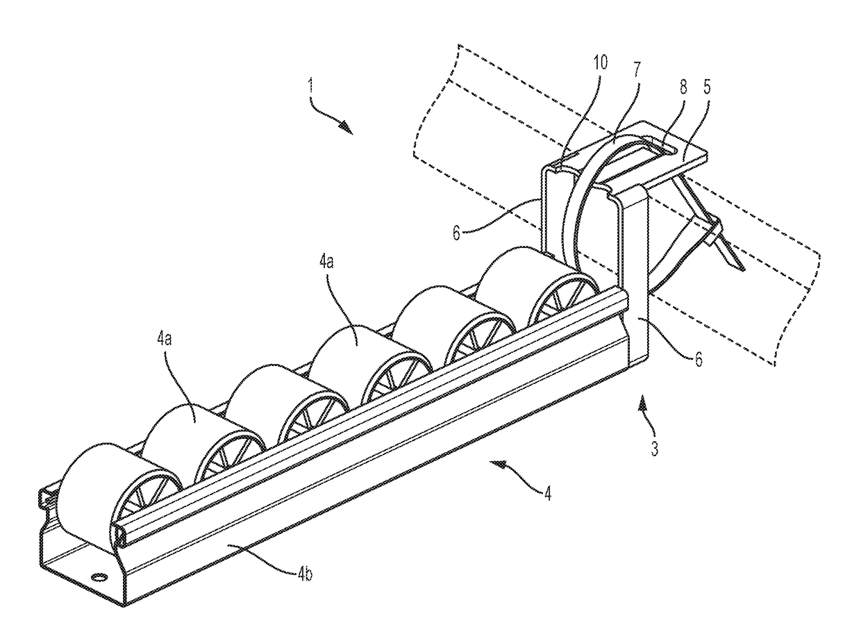
[0006]The purpose of the present invention is to resolve the aforementioned drawbacks by developing a utensil for securing a roller track to a frame of a conveyor installation, which presents the advantage of adapting to any size of the structure of the frame on which the track is supported.

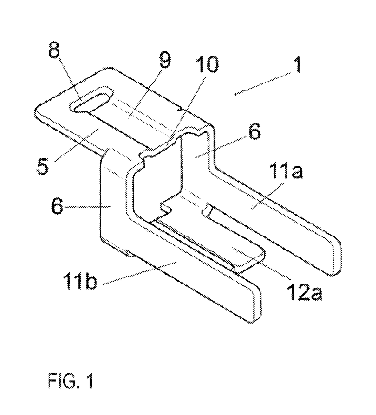
[0007]In line with this objective, according to a first aspect, the present invention provides a utensil for securing a roller track to a frame of a goods conveyor installation, which comprises means for fastening one end of said track, and a base for holding said fastening means, and is characterised in that it comprises a clamp for securing the holding base on the aforesaid structure, said clamp being capable of surrounding said structure to secure said holding base when said holding base leans on the structure.

[0008]The claimed utensil presents the advantage of including a clamp for securing the holding base of the part that fastens the track. This clamp adapts to any size of the structure on ...


PUM


Abstract

Utensil (1) for securing a roller (4a) track (4) to a frame structure of a goods conveyor installation, which comprises means (2,11a,11b,12a,12b) for fastening one end (3) of said track (4), and a base (5) for holding said fastening means (2,11a,11b,12a,12b), that is characterized in that it comprises a clamp (7) for securing said holding base (5) to the aforesaid structure, said clamp (7) being capable of surrounding said structure in order to secure said holding base (5) when said holding base (5) leans on the structure. The utensil presents the advantage of adapting to any size of the structure of the frame on which the track is supported.

Description

[0001]The present invention relates to a utensil for securing a roller track to the frame of a conveyor installation which includes a gravity system for moving goods, such as for example, a system known in the industry by the name of “roller conveyor system or flow track transport system”. It also relates to a roller conveyor system including a plurality of said utensils.BACKGROUND OF THE INVENTION[0002]Roller tracks are normally used in industry to move goods or light packages by gravity along shelving or work surfaces on which a plurality of said tracks have been previously assembled. This type of conveyor system is known in the industry by the name “roller conveyor system or flow track transport system”.[0003]The aforesaid roller tracks comprise a profile that is usually made of galvanised sheet metal or aluminium, substantially shaped like a “U”, wherein the side walls present a plurality of holes for receiving the roller axles.[0004]In the market there are utensils for securing...

Claims


Application Information

Patent Timeline
Patent Type & Authority Patents(United States)
IPC IPC(8): B65G13/11B65G1/02B65G39/12
CPCB65G13/11B65G39/12B65G1/023
Inventor MERINO CASAJUANA, CARLES
Owner DINALAGER
Why Eureka
Try Eureka