Fuel door assembly

a technology for fuel doors and assemblies, applied in the field of fuel door systems, can solve the problems of difficult and time-consuming assembly, low production efficiency, and high manufacturing cost of assembly, and achieve the effects of less subject to malfunction, easy assembly, and low manufacturing cos

Inactive Publication Date: 2007-08-21
LUND MOTION PRODS
View PDF32 Cites 45 Cited by
  • Summary
  • Abstract
  • Description
  • Claims
  • Application Information

AI Technical Summary

Benefits of technology

[0006]One aspect of the present invention is an improved fuel door assembly. The assembly desirably includes a housing, a fuel door and a closing mechanism. Advantageously, certain embodiments of the assembly may be particularly adapted to be inexpensively manufactured out of a minimum number of parts, to be quickly and easily assembled, to be less subject to malfunction due to corrosion of the biasing element or mechanism, and to include a low-profile design that is more compact.
[0010]Another aspect of the present invention is an improved fuel door assembly. The assembly includes a housing, a fuel door and a closing mechanism. Advantageously, the assembly is particularly adapted to be inexpensively manufactured out of a minimum of parts, and to be quickly and easily assembled.
[0014]In accordance with still another preferred embodiment a fuel door assembly comprises a housing that defines an axis of rotation and has a moveable retaining surface that is biased toward the axis of rotation. A fuel door is received in the housing and is rotatable about the axis of rotation between a closed position and an open position. The fuel door has a first cam surface and a second cam surface. The retaining surface contacts one of the first cam surface and the second cam surface to maintain the angular position of the fuel door when the fuel door in either the open position or the closed position.

Problems solved by technology

Unfortunately, such assemblies are often relatively expensive to manufacture, include numerous parts, are difficult and time consuming to assemble, are subject to malfunction due to corrosion, and do not have a compact, low profile design.

Method used


Image

  • Fuel door assembly
  • Fuel door assembly
  • Fuel door assembly

Examples


Embodiment Construction

. 1-9

[0039]Below is a detailed description of the embodiment described in FIGS. 1-9

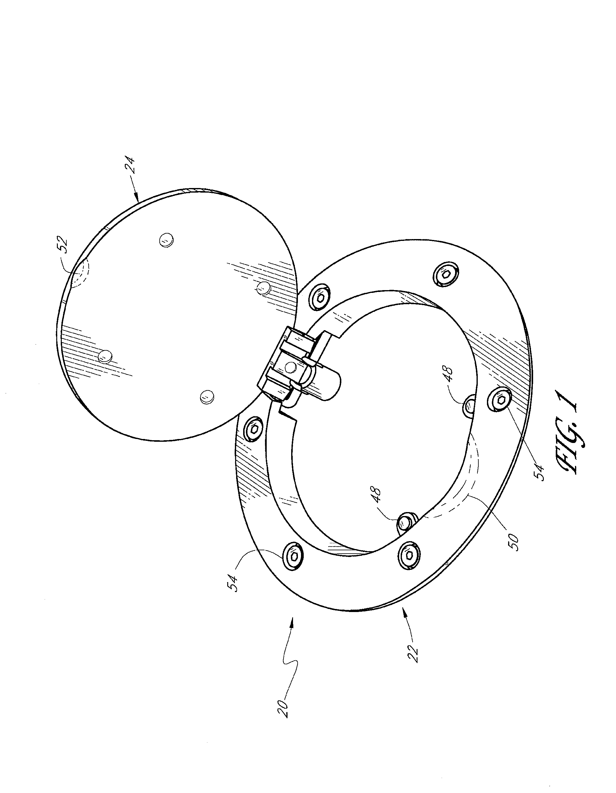
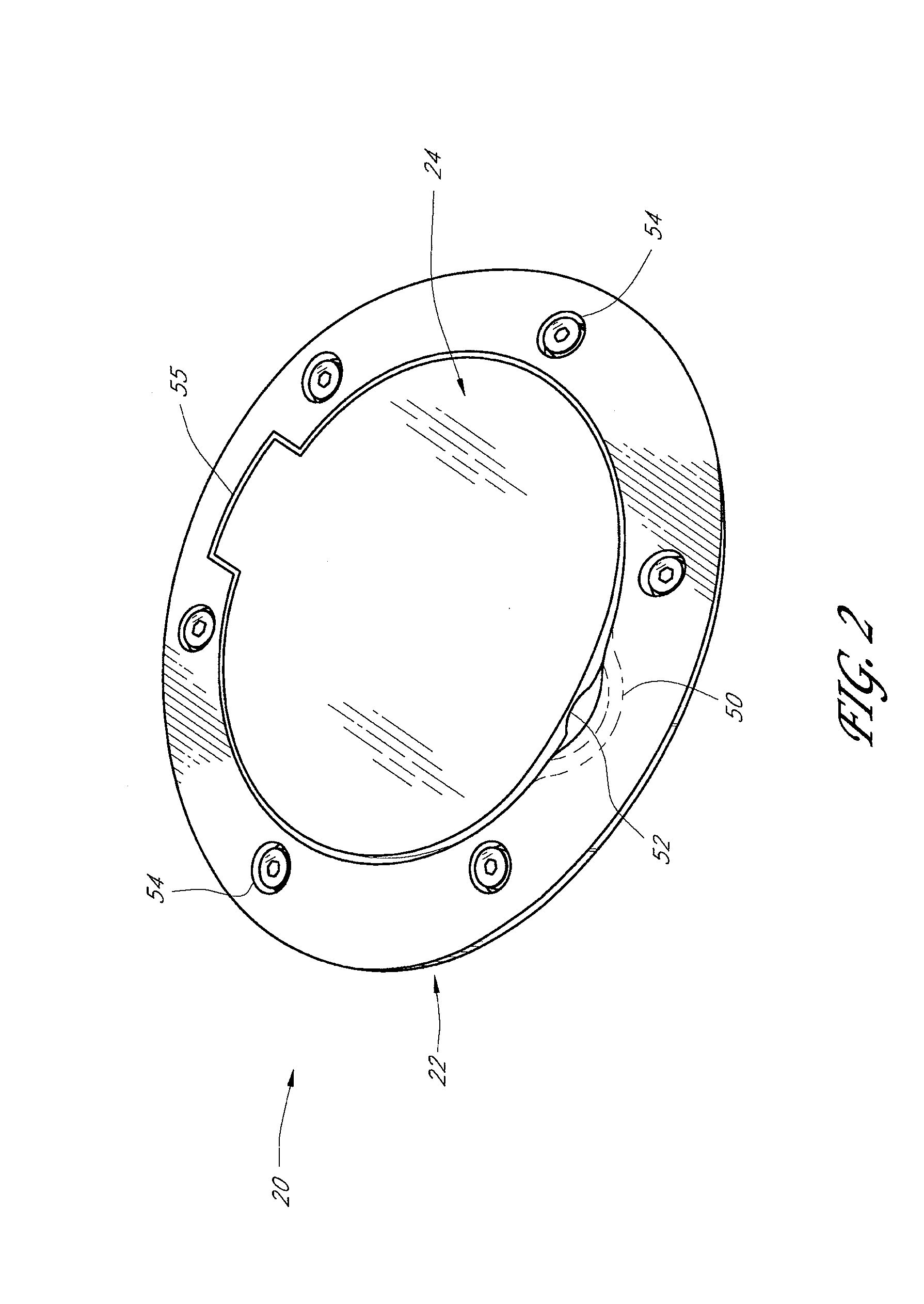
[0040]FIGS. 1-5 depict a fuel door assembly 20 having features in accordance with one preferred embodiment of the invention. The fuel door assembly 20 generally comprises a housing 22 that receives a fuel door 24, which is rotatable through about 80°-100° between a closed position A in which the fuel door is generally flush with the housing (see FIG. 3) and an open position B in which the fuel door permits the entry of a nozzle through an opening in the housing (see FIG. 4). Preferably, the angle between the open position and the closed position is about 90°.

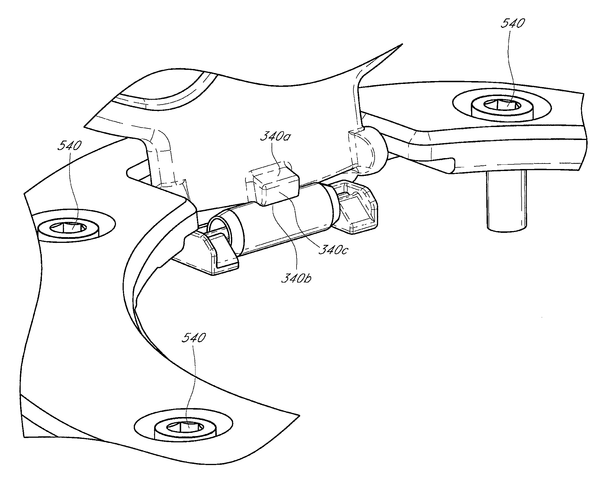
[0041]The fuel door 24 and the housing 22 are shown in greater detail in FIGS. 5, 6 and 7A-7C. The fuel door 24 has a cover portion 26, a lever portion 28 and axle portions 30a, 30b. The lever portion 28 forms a first cam surface or leverage surface 32a and a second cam surface or leverage surface 32b. A peak surface 34, which is preferably curved...


PUM


Abstract

There is described an improved fuel door assembly. In one preferred embodiment, the fuel door comprises a housing that defines an axis of rotation and has a biasing element that is at least partially surrounded by a second interface that forms a cavity that narrows between the ends of the second interface. The fuel door has a first interface that contacts the second interface such that the biasing element urges the fuel door toward the closed position when the fuel door is at the closed position, and urges the fuel door toward the open position when the fuel door is at the open position.

Description

RELATED APPLICATIONS[0001]This application is a continuation-in-part application of U.S. application Ser. No. 11 / 064,032, filed Feb. 22, 2005, now abandoned which is a continuation application of U.S. application Ser. No. 10 / 420,101, filed Apr. 18, 2003, now abandoned which is a continuation application of U.S. application Ser. No. 10 / 090,464, filed Mar. 4, 2002, now abandoned which is a continuation application of U.S. application Ser. No. 09 / 556,374, filed Apr. 24, 2000, now U.S. Pat. No. 6,352,295, which claims priority from U.S. Provisional Application No. 60 / 131,259, filed Apr. 27, 1999, titled FUEL DOOR ASSEMBLY. The disclosures all of which are incorporated by reference.BACKGROUND OF THE INVENTION[0002]1. Field of the Invention[0003]The present invention relates generally to fuel door systems, and more particularly to a fuel door assembly for a motor vehicle or other equipment fueled by gasoline or other fuels or energy sources.[0004]2. Description of the Related Art[0005]Man...

Claims


Application Information

Patent Timeline
Patent Type & Authority Patents(United States)
IPC IPC(8): B60K15/05E05F1/14
CPCB60K15/0406B60K15/05Y10T16/5383B60K2015/053B60K2015/0445
Inventor LEITNER, HORST
Owner LUND MOTION PRODS
Why Eureka
Try Eureka