LED assembly

a technology of led assembly and assembly plate, which is applied in the direction of lighting and heating apparatus, coupling device connection, lighting support device, etc., can solve the problems of long manufacturing time, higher manufacturing cost, and longer connection time, and achieve the effect of convenient and fast assembly

Inactive Publication Date: 2012-02-07
CHEN YA HUEI
View PDF12 Cites 45 Cited by
  • Summary
  • Abstract
  • Description
  • Claims
  • Application Information

AI Technical Summary

Benefits of technology

[0010]The first object of the present invention is to provide an improved LED assembly comprising a frame and a circuit substrate. The frame has a slot, and one or more conductive strips that are formed on the inner side of the elongated inverted L-shaped structure of the frame. The conductive strips are connected with a power source and may be engaged with the conductive strips disposed on the circuit substrate. In assembly, the circuit substrate is slid into the slot of the frame so that each of the conductive strips of the circuit substrate is engaged with the corresponding conductive strip of the frame. Therefore, electricity from the electric source may be fed from the source through the conductive strip of the frame and the conductive strip of the circuit substrate and then to the light-emitting units so that each of the light-emitting units may be powered up and emit light. Consequently, the goal of easy and fast assembly may be reached.
[0011]The second object of the present invention is to provide an improved LED assembly that has the advantages of simple structure, easy assembly and high usefulness.

Problems solved by technology

However, more heat is generated by LED when it is lit; therefore, a heat-dissipating module must be used to dissipate the heat into the ambient air.
1. In the prior art, LEDs are first disposed on an aluminum substrate and then the aluminum substrate is fastened onto a heat-dissipating module by screws or glue. Therefore, longer time is needed in manufacturing and cost of manufacturing is higher.
2. Also, each LED has to be electrically connected with a power source. Such connection takes longer time.

Method used


Image

  • LED assembly
  • LED assembly
  • LED assembly

Examples


first embodiment

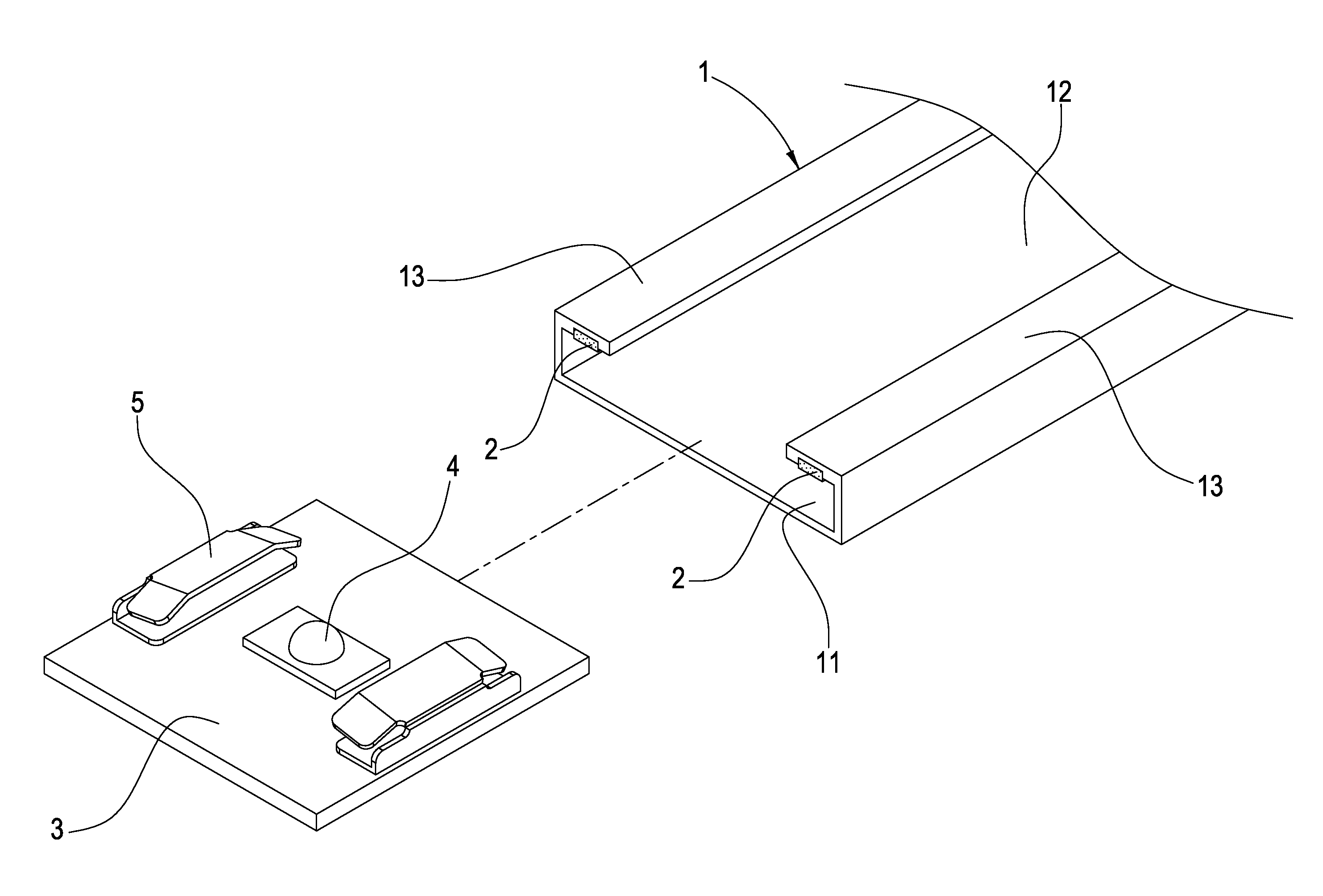
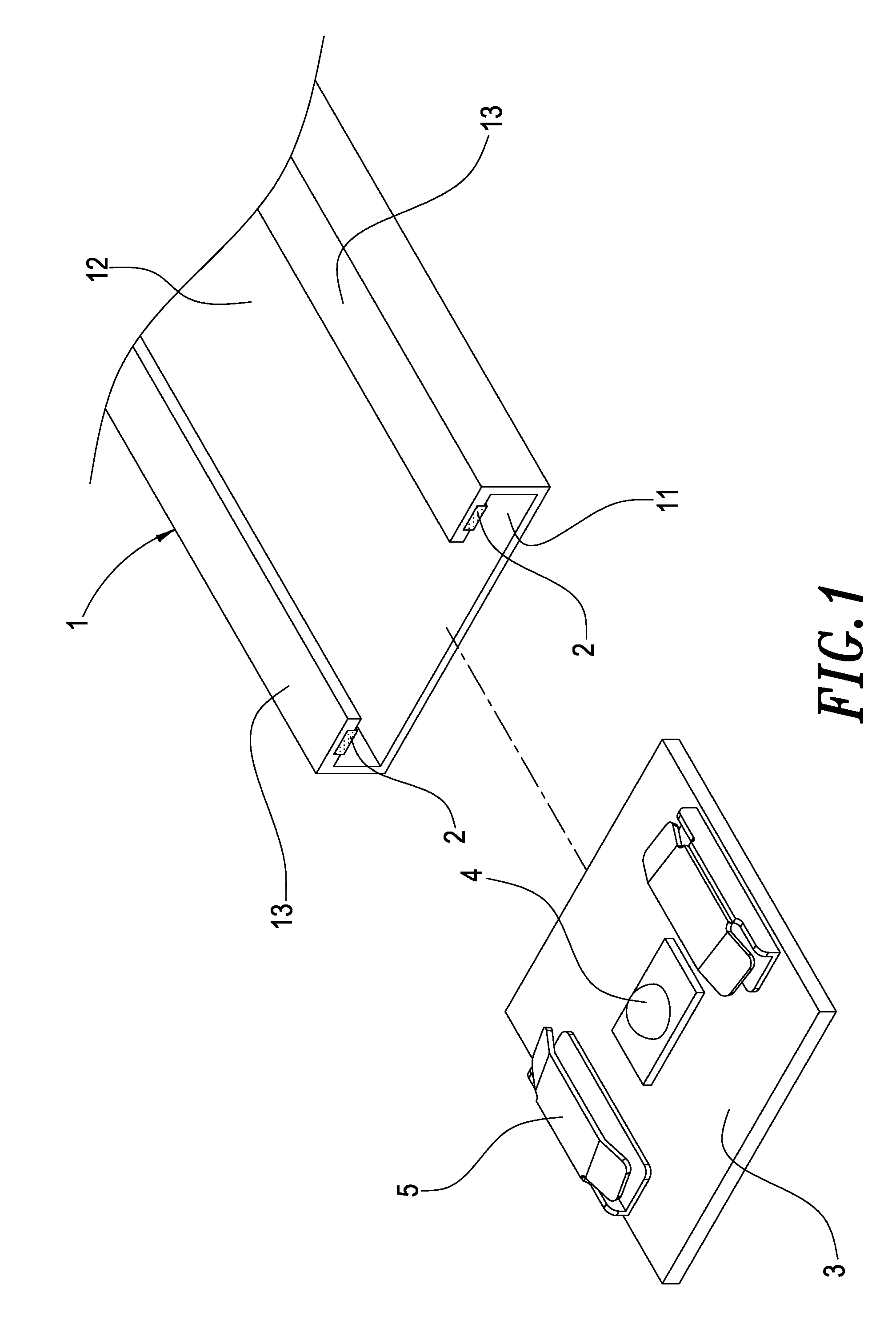
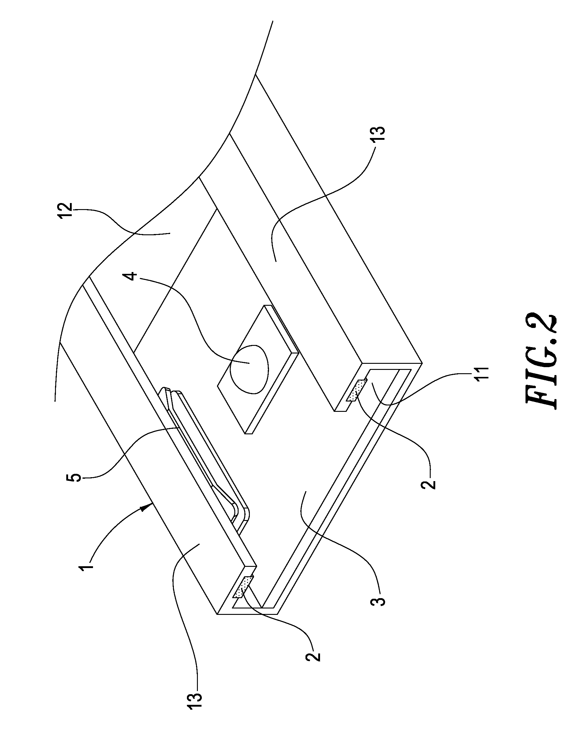
[0025]Please see FIGS. 1, 2 and 3, which are the drawings schematically illustrating the present invention. The improved LED assembly of the present invention comprises a frame 1 and a circuit substrate 3.

[0026]The frame 1 has a slot 11. The slot 11 has an opening 12 on its upper surface. An elongated inverted L-shaped structure 13 is formed on either side of the opening 12. One or more conductive strips 2 are formed on the inner side of the elongated inverted L-shaped structure 13. The positive lead of a power source is connected with some of the conductive strips 2, and the negative lead of the power source is connected with the other conductive strips 2. Preferably, there are two or more conductive strips 2.

[0027]The circuit substrate 3 has one or more light-emitting units 4 and two or more conductive strips 5. These conductive strips 5 may engage with the conductive strips 2 of the frame 1, and the number of the former is the same with that of the latter. In addition, these cond...

second embodiment

[0031]Please refer to FIG. 6, which illustrates the present invention. An opening is formed on the frame 1. In assembly, the circuit substrate 3 containing the light-emitting units and conductive strips may be fitted onto the frame 1 through the slot 11 so that the conductive strips 5 may be engaged with the conductive strips 2 of the frame 1. A flat cover 14 may be used to seal off the opening and to press the conductive strips 5 downwards so as ensure the electrical contact between each conductive strip 5 and the corresponding conductive strip 2.

[0032]Please refer to FIGS. 7 and 8, which illustrate a third embodiment of the present invention. In contrast to the first embodiment illustrated in FIG. 1, three light-emitting units 4 (emitting red, green and blue light) and four conductive strips 5 are disposed on the circuit substrate 3. One of the four conductive strips 5 is connected to the positive prongs of the three light-emitting units 4 through connective wire or circuit design...


PUM


Abstract

An improved LED assembly comprises a frame and a circuit substrate. The frame has a slot, which has an opening on the upper surface of the frame. An elongated inverted L-shaped structure is formed on either side of the opening, and one or more conductive strips are formed on the inner side of the elongated inverted L-shaped structure. Therefore, electricity may be supplied to the conductive strips of the frame. In assembly, the circuit substrate is slid into the slot of the frame so that each of the conductive strips of the circuit substrate is engaged with the corresponding conductive strip of the frame. Therefore, electricity from the electric source may be fed from the source through the conductive strip of the frame and the conductive strip of the circuit substrate and then to the light-emitting units so that each of the light-emitting units may be powered up.

Description

BACKGROUND OF THE INVENTION[0001]1. Field of the Invention[0002]The invention generally relates to an LED assembly. More particularly, the invention relates to an improved LED assembly that light-emitting units may be lit up after the circuit substrate is fitted onto the frame.[0003]2. Description of the Prior Art[0004]LED has the advantages of long service life, high energy efficiency, durability, resistance to vibrations, reliability, compactness, fast response and the fact that it may be massively produced. Therefore, LED has been used for the purpose of illumination. However, more heat is generated by LED when it is lit; therefore, a heat-dissipating module must be used to dissipate the heat into the ambient air. Whence, such heat-dissipating module is an indispensable part of an LED assembly.[0005]The LED assembly of the prior art has the following two disadvantages in assembling:[0006]1. In the prior art, LEDs are first disposed on an aluminum substrate and then the aluminum s...

Claims


Application Information

Patent Timeline
Patent Type & Authority Patents(United States)
IPC IPC(8): F21S4/00F21V21/005F21V21/34
CPCF21V19/0045F21V29/004F21V29/763F21V29/73F21K9/00H01R25/14Y10S362/80F21Y2101/02F21Y2103/10F21Y2115/10F21V19/001F21V21/35H01L25/0753
Inventor CHEN, YA-HUEI
Owner CHEN YA HUEI
Why Eureka
Try Eureka