Moving-magnet type linear motor

a linear motor and moving magnet technology, applied in the field of linear motors, can solve the problems of low heat conduction efficiency between the coreless coil and the coolant, poor responsiveness, and increase the mass of the moving magnet body, so as to improve manufacturing efficiency and reduce costs

Inactive Publication Date: 2010-06-08
JTEKT CORP
View PDF14 Cites 45 Cited by
  • Summary
  • Abstract
  • Description
  • Claims
  • Application Information

AI Technical Summary

Benefits of technology

[0008]It is therefore a primary object of the present invention to provide a moving-magnet type linear motor in which a movable member is light in weight and high in responsiveness and which is capable of removing heat generated by drive current applied to coreless coils and of efficiently generating a powerful propelling force as a result of suppressing the generation of eddy current.
[0010]With this construction, since coolant is fed to the at least one cooling member jointed thermally closely with the coreless coil to be circulated through the fluid passage formed in the at least one cooling member, the heat generated in the coreless coil due to the application of drive current thereto can be removed efficiently. Further, the at least one cooling member is a one-piece component in which the sheet-like protrusions jointed with the coreless coil is integrated with the base end portion in which the coolant flows. This enables the at least one cooling member to be assembled to the stator base easily and quickly, so that there can be attained improvement in manufacturing efficiency and a substantial reduction in cost.

Problems solved by technology

However, in the technology of the aforementioned Japanese published utility model application, the moving-magnet body is configured by the column permanent magnet which surrounds the circumferential surface of the through shaft member, and this gives rise to a drawback that the mass of the moving-magnet body increases to result in a poor responsiveness.
Further, in the technology of the aforementioned Japanese unexamined, published patent application, the cross-section of each support member in which the pipe conduit is provided for flowing coolant therethrough is so larger as to make the heat from the coreless coils spread over the whole of each support member, and this gives rise to a drawback that the heat conduction between the coreless coils and the coolant is low in efficiency.
In addition, consideration should have been taken into a universal problem that when a metal member moves across magnetic flux, eddy current is generated to decrease the propelling force for the moving member.

Method used


Image

  • Moving-magnet type linear motor
  • Moving-magnet type linear motor
  • Moving-magnet type linear motor

Examples


Embodiment Construction

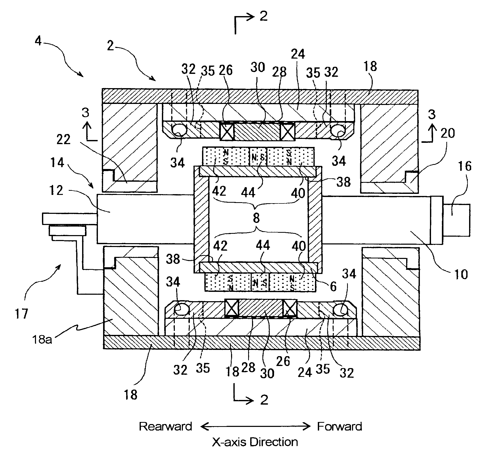
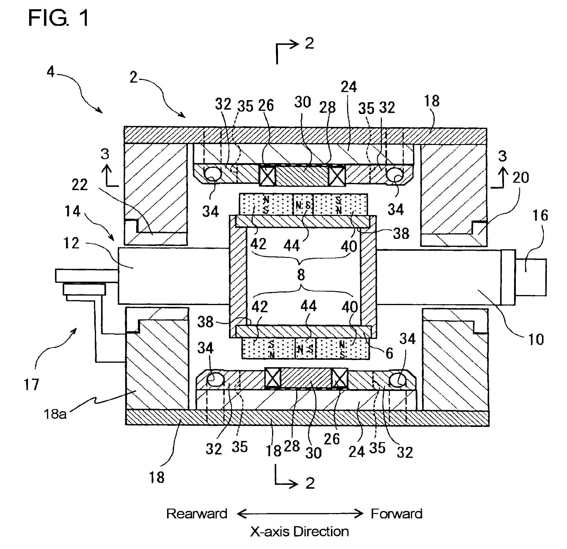
[0020]Hereafter, a tool moving device with a moving-magnet type linear motor in one embodiment according to the present invention will be described with reference to the accompanying drawings. FIG. 1 is a longitudinal sectional view showing the construction of the tool moving device, and FIG. 2 is a cross-sectional view taken along the line 2-2 in FIG. 1. The linear motor designated by reference numeral 2 is composed of primary components on a stationary side and secondary components on a moving side movable relative to the primary components.

[0021]As shown in FIG. 1, the tool moving device designated by reference numeral 4 is provided with a movable body 14, which is composed of a magnet yoke 6 taking the shape of a hollow or empty box made of a magnetic material such as, e.g., iron or steel, a plurality of magnet constructs 8a-8d (collectively designated as 8 from time to time) made of permanent magnets attached to the circumferential surface of the magnet yoke 6, and a pair of su...


PUM


Abstract

A moving-magnet type linear motor is provided with cooling blocks which are attached to each of stator bases alongside a coreless coil and which allow coolant to flow therethrough for cooling the coreless coil. Each of the cooling blocks has in a base end portion thereof a fluid passage for flowing coolant and at an extreme end portion thereof a plurality of sheet-like protrusions like fins which are arranged alongside a part of the circumferential surface of the coreless coil with a clearance between each protrusion and the next thereto. Each cooling block is thermally closely jointed with the coreless coil at the extreme ends of the sheet-like protrusions.

Description

INCORPORATION BY REFERENCE[0001]This application is based on and claims priority under 35 U.S.C. 119 with respect to Japanese patent application No. 2007-055540 filed on Mar. 6, 2007, the entire content of which is incorporated herein by reference.BACKGROUND OF THE INVENTION[0002]1. Field of the Invention[0003]The present invention relates to a linear motor for use in various industrial machinery such as, for example, machine tools, electric component mounting apparatus or semiconductor-related apparatus. Particularly, it relates to a moving-magnet type linear motor which is constructed to take a field system as moving element and an armature as stator.[0004]2. Discussion of the Related Art[0005]As a moving-magnet type linear motor which takes a field magnet as moving element and an armature (coreless coils) as stator, there has been known one which is described in Japanese published utility model application No. 07-30585. This is of the construction that a moving-magnet body is con...

Claims


Application Information

Patent Timeline
Patent Type & Authority Patents(United States)
IPC IPC(8): H02K41/00
CPCH02K41/03H02K5/18H02K5/20H02K2201/18H02K9/22H02K9/227H02K5/203
Inventor MUKAIDE, NAOMASA
Owner JTEKT CORP
Why Eureka
Try Eureka