Two-stage valve

a two-stage valve and valve body technology, applied in the direction of fluid pressure control, process and machine control, instruments, etc., can solve the problems of not allowing any intermediate position of such a shutter, consuming a substantial amount of electrical energy in order to be able to operate correctly, and the known two-stage valve is particularly bulky and heavy. , to achieve the effect of simple, cost-effective and particularly functional manner

Active Publication Date: 2018-01-30
DOLPHIN FLUIDICS SRL
View PDF11 Cites 1 Cited by
  • Summary
  • Abstract
  • Description
  • Claims
  • Application Information

AI Technical Summary

Benefits of technology

[0013]The purpose of the present invention is therefore to make a two-stage valve, both with on / off function, and with proportional function, which is able to solve the aforementioned drawbacks of the prior art in an extremely simple, cost-effective and particularly functional manner.

Problems solved by technology

This means that the state taken up by the actuator of the valve, typically consisting of a solenoid, can cause the closure and the complete opening of the valve shutter, but it does not allow any intermediate position of such a shutter.
A known two-stage valve, therefore, is particularly bulky and heavy, since it consists of two distinct valves interconnected through suitable channels.
In addition, although it is provided with an actuator that controls only the shutter of the pilot valve, a known two-stage valve in any case consumes a substantial amount of electrical energy in order to be able to operate correctly.

Method used


Image

  • Two-stage valve
  • Two-stage valve
  • Two-stage valve

Examples


Embodiment Construction

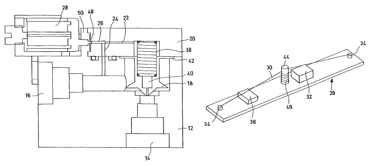
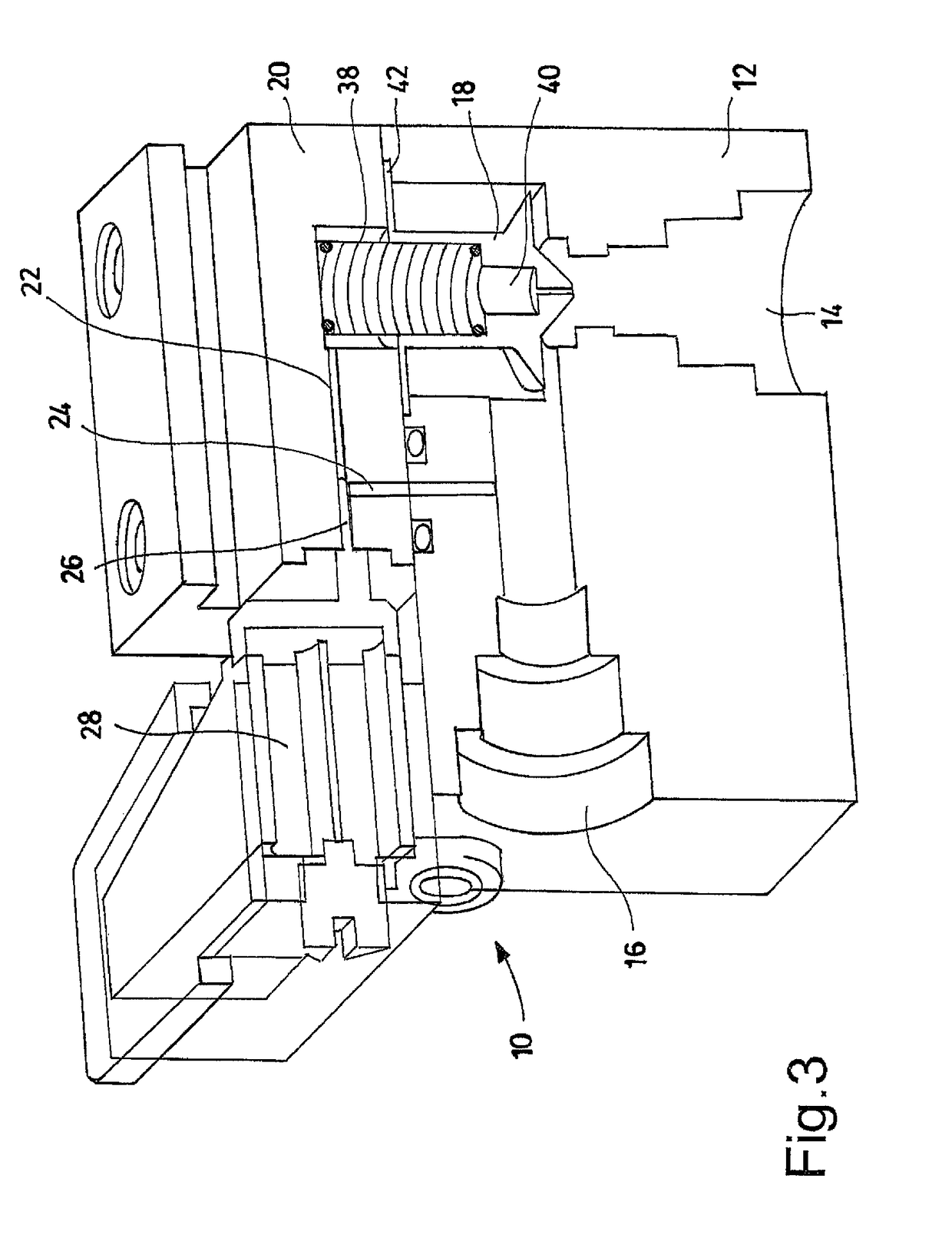
[0036]With reference to the figures, some embodiments of the two-stage valve according to the present invention are shown, wholly indicated with reference numeral 10. The two-stage valve 10 comprises a first stage, constituted by a main valve body 12 provided with at least one fluid inlet duct 14 for inletting fluid into the main valve and with at least one fluid outlet duct 16 for outletting fluid out from the main valve. Between the fluid inlet duct 14 of the main valve and the fluid outlet duct 16 of the main valve at least one shutter element 18 of the main valve is interposed, configured to put selectively in fluid communication such a fluid inlet duct 14 of the main valve with such a fluid outlet duct 16 of the main valve.

[0037]The two-stage valve 10 also comprises a second stage, constituted by a pilot valve body 20 provided with at least one fluid inlet duct 22 for inletting fluid into the pilot valve and with at least one fluid outlet duct 24 for outletting fluid out from t...


PUM


Abstract

The present invention describes a two-stage valve comprising a first stage constituted by a main valve body provided with at least one fluid inlet duct and with at least one fluid outlet duct, between which is interposed at least one shutter element configured to put selectively in fluid communication such ducts. The valve comprises a second stage constituted by a pilot valve body provided with at least one fluid inlet duct and with at least one fluid outlet duct, between which is interposed at least one shutter element configured to put selectively in communication such ducts. The opening of the shutter element of the pilot valve generates a fluid flow passing through the fluid inlet duct of the pilot valve and the fluid outlet duct of the pilot valve, the pressure of such a fluid flow generating the opening of the shutter element of the main valve. The shutter element of the pilot valve is actuated by an actuator device comprising at least one wire made of a shape-memory alloy, capable of applying a force onto the shutter element of the pilot valve as a consequence of a temperature variation determined by the Joule effect by the flow of an electric current through such a wire.

Description

FIELD OF THE INVENTION[0001]The present invention refers in general to a control device for a hydraulic circuit and, more specifically, to a two-stage valve configured to detect and manage the essential parameters of a fluid flowing in a hydraulic circuit.BACKGROUND OF THE INVENTION[0002]A hydraulic circuit comprises two essential components that carry out the conversion of mechanical energy into hydraulic energy and vice-versa. These two components consist of a pump and a motor. In a hydraulic circuit, in addition to these two components, it is required for there to be devices that carry out a control action on the fluid. Due to operating requirements of the circuits it is thus necessary to intervene on the essential hydraulic magnitudes of the fluid, in other words pressure and flow rate, as well as on the direction of the fluid flow.[0003]The devices proposed to perform this control function of the fluid are called valves, which can be grouped into three main categories:[0004]dir...

Claims


Application Information

Patent Timeline
Patent Type & Authority Patents(United States)
IPC IPC(8): F16K31/02F16K31/04G05D7/06
CPCG05D7/0635F16K31/04F16K31/02F16K31/406F16K31/025F15B13/0433G05D16/2097
Inventor ANDREIS, DIEGO
Owner DOLPHIN FLUIDICS SRL
Why Eureka
Try Eureka