Supercharge Your Innovation With Domain-Expert AI Agents!

Optical system, apparatus and method for operating an apparatus using helmholtz reciprocity

a technology of optical system and reciprocity, applied in the field of optical system, can solve the problems of preventing the discovery of general scenes, unable to achieve unique disparity assignment, and low depth information resolution

Active Publication Date: 2018-01-30
SONY CORP
View PDF4 Cites 1 Cited by
  • Summary
  • Abstract
  • Description
  • Claims
  • Application Information

AI Technical Summary

Benefits of technology

The patent is about an optical system that can capture images of a scene with objects in them using a special technique called Helmholtz reciprocity. The system includes an illumination unit that emits light and an imaging unit that receives the light from the illumination unit. The system also includes a computing unit that analyzes the light in the images and can determine information about the depth and position of the objects in the scene. This technology allows for the creation of more robust and accurate images of objects in a scene.

Problems solved by technology

Typically, the resolution of the depth information is low and elaborate computations obtain the depth information from the two-dimensional images.
If discontinuous surfaces with large height steps are used, grating or phase ambiguities arise and a unique disparity assignment may not be possible.
In addition, at object boundaries and rapid changes in depth singularities of the derivative of the depth occur, which may prevent finding a solution for general scenes.

Method used


Image

  • Optical system, apparatus and method for operating an apparatus using helmholtz reciprocity
  • Optical system, apparatus and method for operating an apparatus using helmholtz reciprocity
  • Optical system, apparatus and method for operating an apparatus using helmholtz reciprocity

Examples


Embodiment Construction

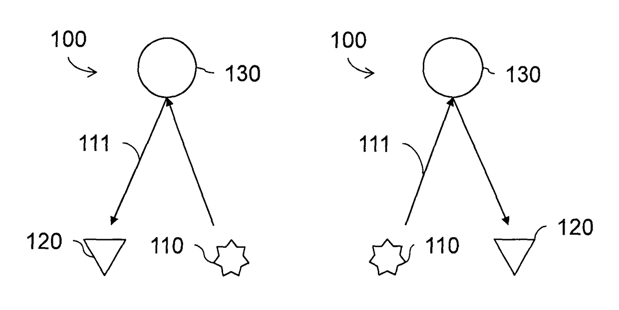
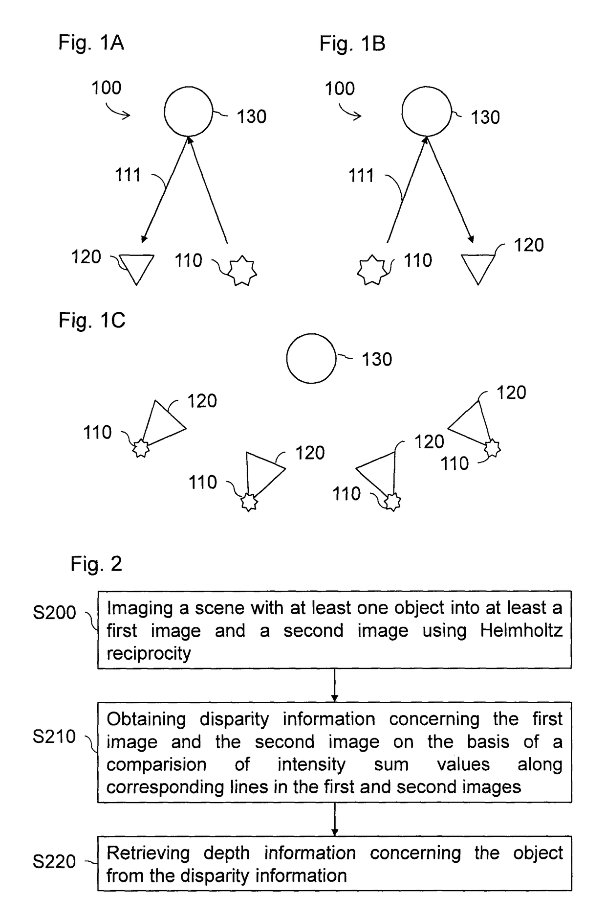
[0029]FIGS. 1A and 1B illustrate an optical system 100 that includes at least one illumination unit 110 and at least one imaging unit 120. The illumination unit 110 illuminates a scene including at least one object 130. For example, the scene may include objects 130 located in front of a screen, which are illuminated in order to obtain depth profiles of the objects 130. Such a setup may for example be used to inspect workpieces or tools used in industrial applications. According to another embodiment the scene may be a room in which an entertainment system such as a game console or a television is located. Then, objects 130 within the scene, e.g. furniture or persons within the room, are illuminated to detect distances between the objects and the illumination unit 110. From the detected distances a position of the illumination unit 110 may be determined, which is used to control the entertainment system.

[0030]The illumination unit 110 may be any light source suitable for illuminatin...


PUM


Abstract

An optical system includes an illumination unit and an imaging unit configured to image a scene including at least one object into a first image and a second image by using Helmholtz reciprocity. The illumination unit is configured to emit light into at least one light emitting solid angle and the imaging unit is configured to receive light from a light receiving solid angle. The light receiving solid angle is at least as large as each of the light emitting solid angles.

Description

BACKGROUND[0001]The present disclosure relates to an optical system configured to capture a scene using Helmholtz reciprocity. The disclosure further relates to an apparatus comprising an optical system as well as to a method of operating an apparatus comprising the optical system.DESCRIPTION OF RELATED ART[0002]Stereoscopic imaging systems reconstruct three-dimensional depth information from two or more images of an object captured at different viewing angles. Typically, the resolution of the depth information is low and elaborate computations obtain the depth information from the two-dimensional images. Common approaches for depth acquisition are passive stereoscopic imaging, fringe projection and structured light. Stereoscopy uses at least two pairs of camera images separated by a baseline and after an image rectification step, the scene depth is acquired by matching scene features along corresponding epipolar lines. The resulting disparity measuring the pixel offset of related s...

Claims


Application Information

Patent Timeline
Patent Type & Authority Patents(United States)
IPC IPC(8): G06T7/593H04N13/00
CPCH04N13/0253H04N13/0207G06T7/593H04N2013/0081H04N13/254H04N13/207
Inventor KOEHLE, RODERICKKAMM, MARKUS
Owner SONY CORP
Features
  • R&D
  • Intellectual Property
  • Life Sciences
  • Materials
  • Tech Scout
  • Unparalleled Data Quality
  • Higher Quality Content
  • 60% Fewer Hallucinations
Learn More