X-ray detector for electron microscope

a detector and electron microscope technology, applied in the field of x-ray detectors, can solve the problems of difficult positioning of x-ray detectors close to the sample, insufficient ice-free surface of the detector, and inability to achieve high-resolution tem configuration, etc., to achieve the effect of improving detection capabilities

Active Publication Date: 2011-12-20
FEI CO
View PDF30 Cites 39 Cited by
  • Summary
  • Abstract
  • Description
  • Claims
  • Application Information

AI Technical Summary

Benefits of technology

[0007]An object of the invention, therefore, is to provide an x-ray detector having improved detection capabilities.
[0008]A preferred embodiment uses multiple detectors arranged in a ring within a specimen chamber to provide a large solid angle of collection. The detectors preferably include a shutter and a cold shield that reduce ice formation on the detector. By providing detectors surrounding the sample, a large solid angle is provided for improved detection and x-rays are detected regardless of the direction of sample tilt.

Problems solved by technology

The heat generated by the circuitry provides a temperature difference of only about five degrees, which may not be adequate to maintain an ice-free surface on the detector.
Periodically heating the detector above its operating temperature does not stop the build-up of ice during operation and requires periodic interruption of the system operation to remove the ice.
In a transmission electron microscope, the pole pieces and sample holder take up most of the space around the sample and it can be difficult to position X-ray detectors close to the sample to increase the solid angle.
This configuration is not normally possible in a high-resolution TEM.

Method used


Image

  • X-ray detector for electron microscope
  • X-ray detector for electron microscope
  • X-ray detector for electron microscope

Examples


Embodiment Construction

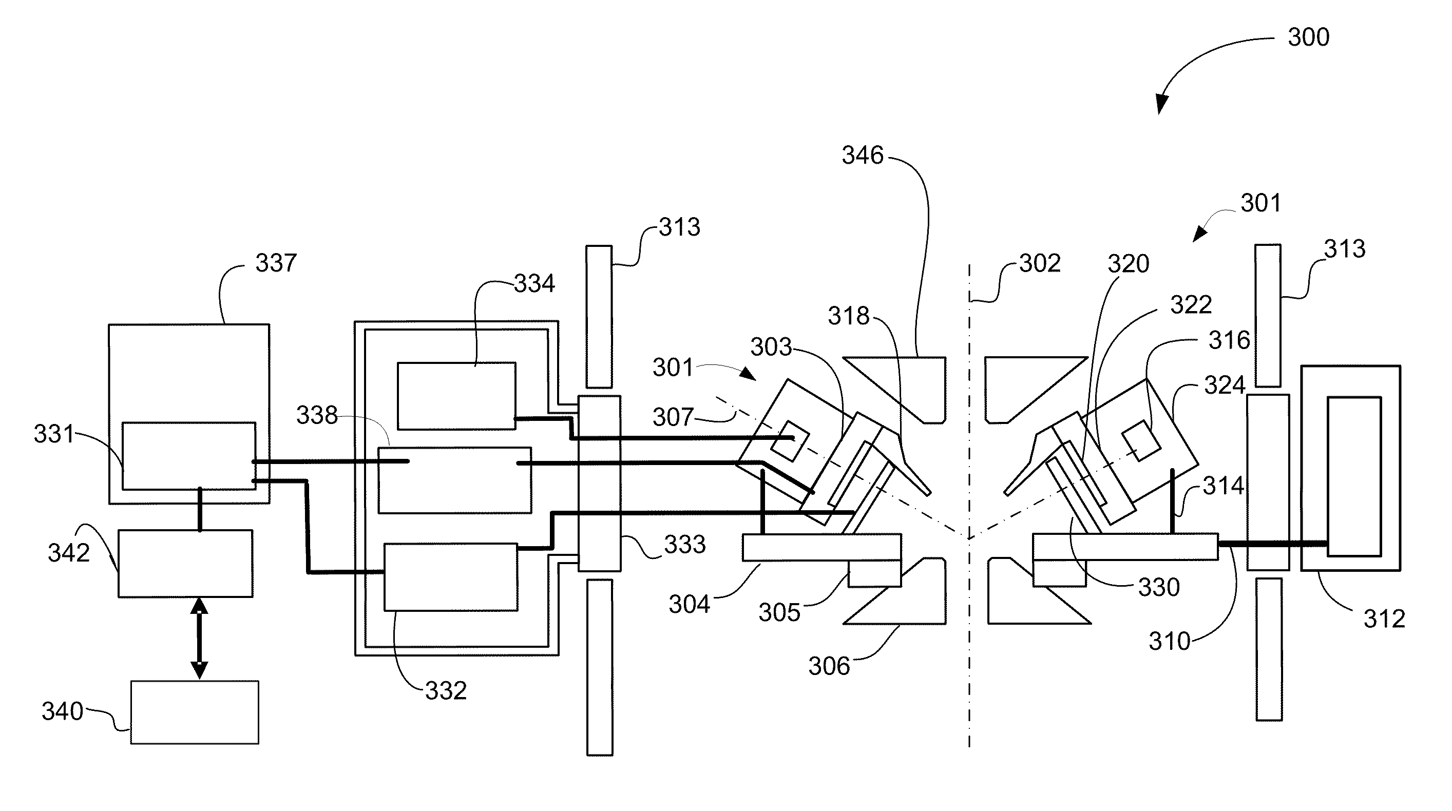
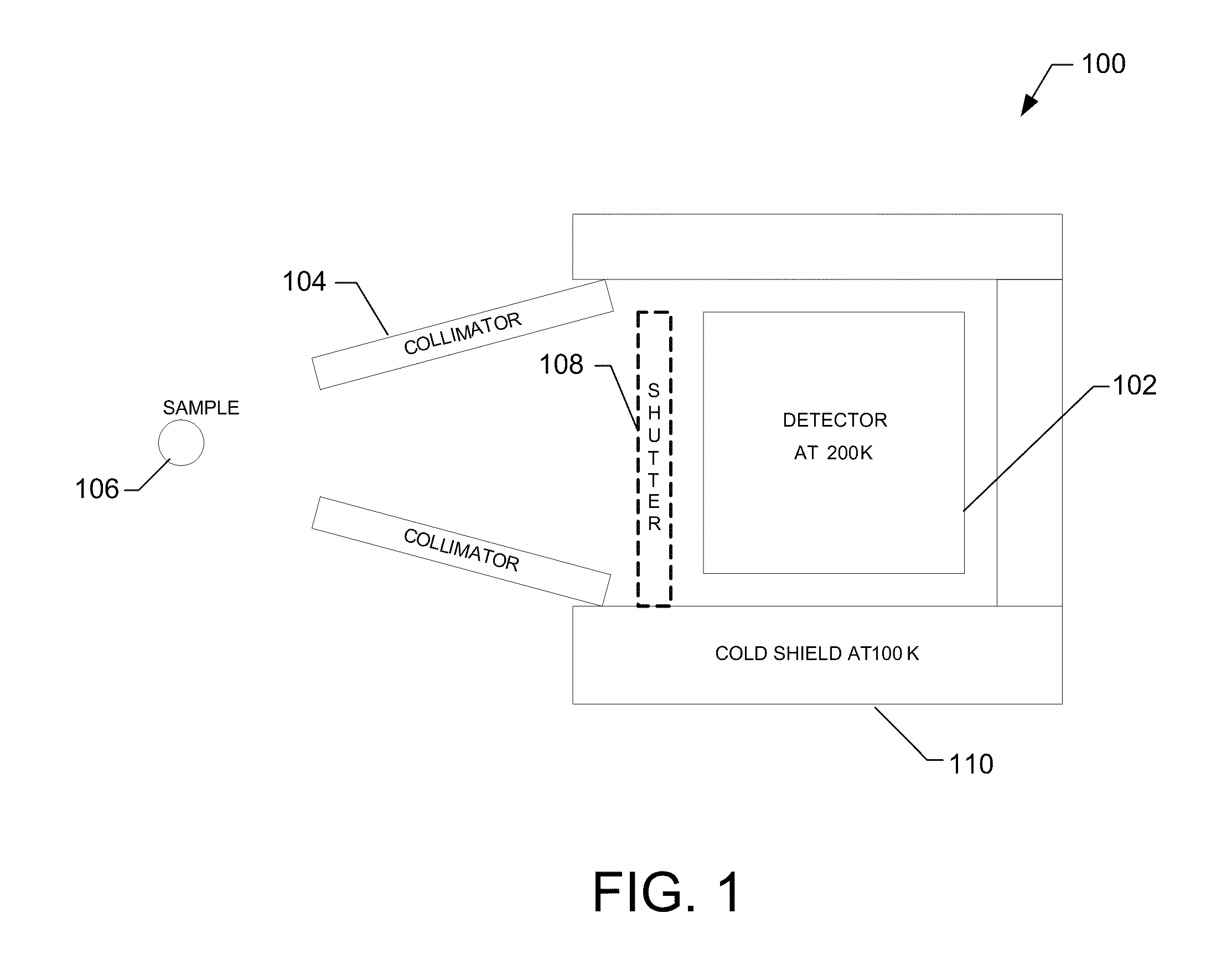
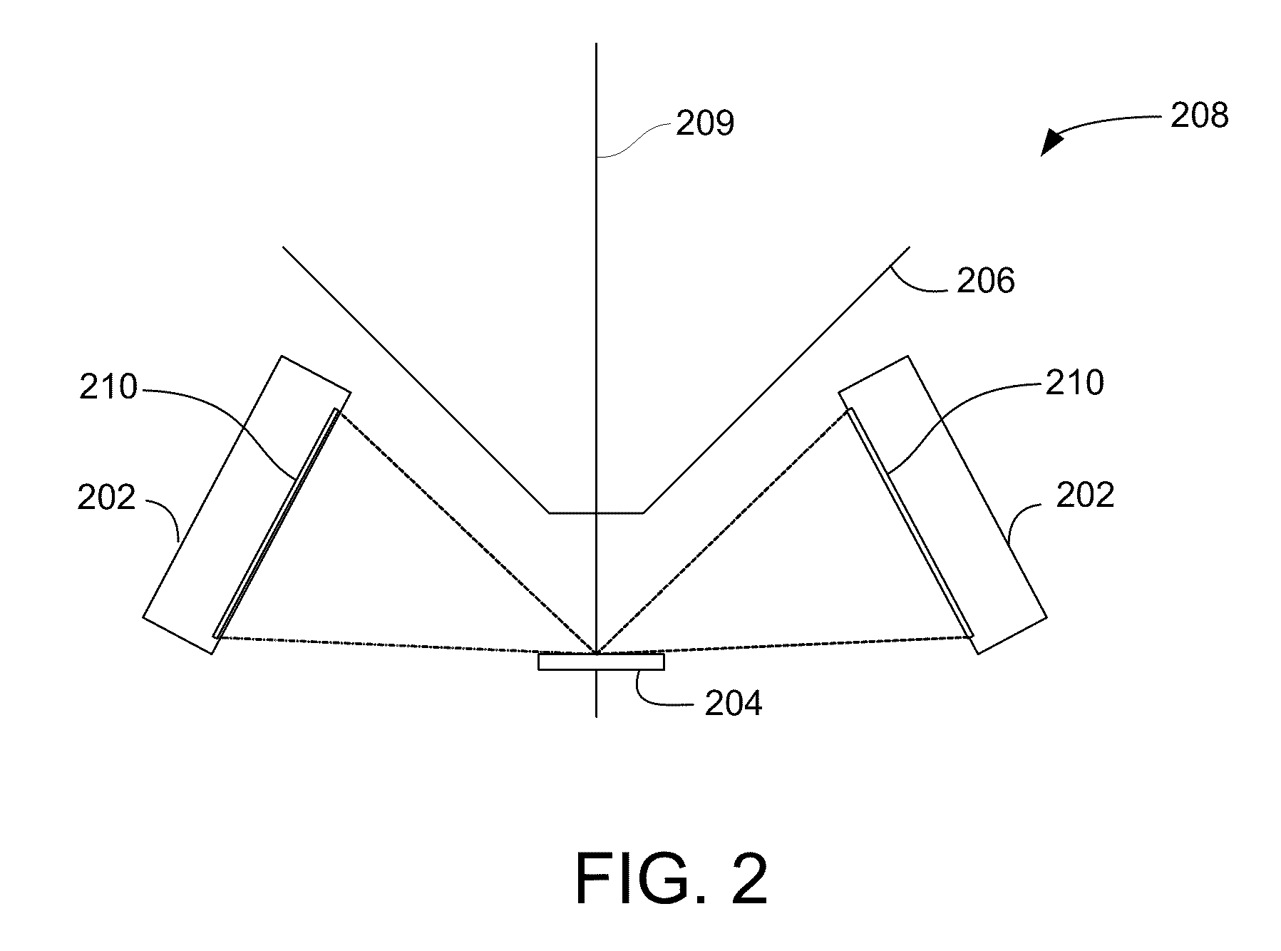
[0017]A preferred embodiment uses multiple detector assemblies arranged in a ring within a specimen chamber to provide a large solid angle of collection. FIG. 1 shows schematically a preferred embodiment of one of the multiple detector assemblies 100. Each detector assembly 100 includes a SDD detector 102 having an active area of preferably greater than 10 mm2, more preferably greater than 20 mm2, and even more preferably about 30 mm2. In some embodiments, each detector includes an active area of between 50 mm2 and 100 mm2. The detector of FIG. 1 includes a collimator 104 that prevents stray x-rays from entering the detector, ensuring that the signal from the detector corresponds to the x-rays emitted from a sample 106. A mechanical shutter 108, shown in the closed position, prevents electrons and low-energy x-rays from damaging the detector when it is not in use.

[0018]The SDD detector 102 is cooled to about 200 K using liquid nitrogen and is surrounded by a cold shield 110 maintain...


PUM


Abstract

Multiple detectors arranged in a ring within a specimen chamber provide a large solid angle of collection. The detectors preferably include a shutter and a cold shield that reduce ice formation on the detector. By providing detectors surrounding the sample, a large solid angle is provided for improved detection and x-rays are detected regardless of the direction of sample tilt.

Description

[0001]This application claims priority from U.S. Provisional Pat. App. No. 61 / 122,295, which is hereby incorporated by reference.TECHNICAL FIELD OF THE INVENTION[0002]The present invention relates to x-ray detectors, and in particular, to an x-ray detector for an electron microscope.BACKGROUND OF THE INVENTION[0003]Electron probe microanalyzers and electron microscopes having an attached x-ray spectrometer are used to determine the composition of microscopic or nanoscopic regions of a surface. The detectors determine the energy or wavelengths of x-rays emitted from the sample and infer the composition of material under the electron beam from the energy or wavelength of the x-rays. Detectors that use a crystal to disperse and analyze x-rays of different wavelengths are referred to as wavelength dispersive spectrometers (WDS) and detectors that measure the energy of incoming x-rays are referred to as energy dispersive spectrometers (EDS). While a WDS can provide better resolution and ...

Claims


Application Information

Patent Timeline
Patent Type & Authority Patents(United States)
IPC IPC(8): H01J37/244H01J37/26
CPCH01J37/244H01J37/26H01J37/28H01J2237/002H01J2237/28H01J2237/2802G01N23/225H01J2237/2442
Inventor VON HARRACH, HANNO SEBASTIANFREITAG, BERTDONA, PLEUN
Owner FEI CO
Why Eureka
Try Eureka