Output current monitor circuit for switching regulator

a current monitor and switching regulator technology, applied in the direction of electric variable regulation, pulse manipulation, instruments, etc., can solve the problems of sensing error, power consumption is also a key design requirement, etc., and achieve the effect of minimal power consumption

Active Publication Date: 2018-02-06
DIALOG SEMICON UK
View PDF15 Cites 5 Cited by
  • Summary
  • Abstract
  • Description
  • Claims
  • Application Information

AI Technical Summary

Benefits of technology

[0019]It is desirable to provide a solution with improved sampling timing.
[0020]It is desirable to provide a solution with improved accuracy of the output current monitor.

Problems solved by technology

Additionally, power consumption is also a key design requirement.
So the center of sampling timing is shifted by Td1 / 2 from the center of NMOS on-timing, and it causes sensing error.

Method used


Image

  • Output current monitor circuit for switching regulator
  • Output current monitor circuit for switching regulator
  • Output current monitor circuit for switching regulator

Examples


first embodiment

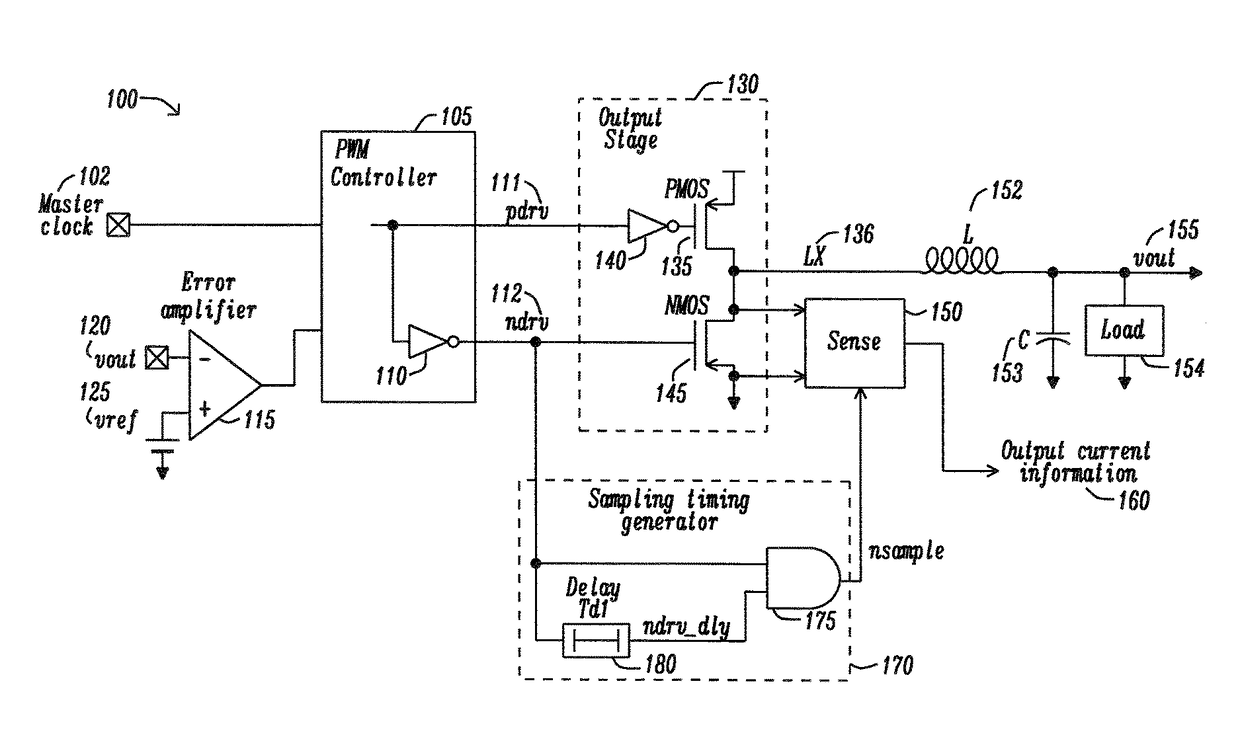
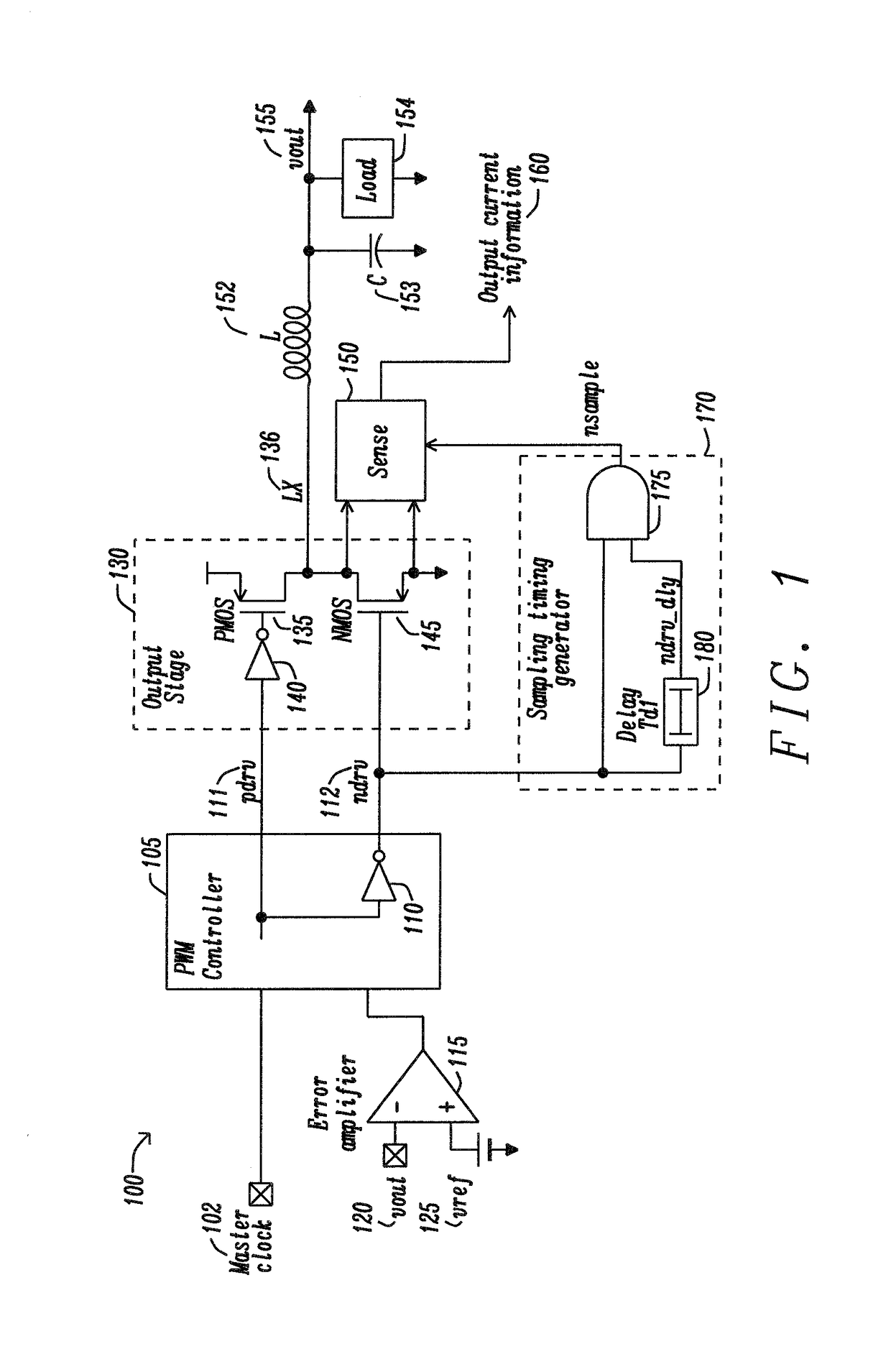
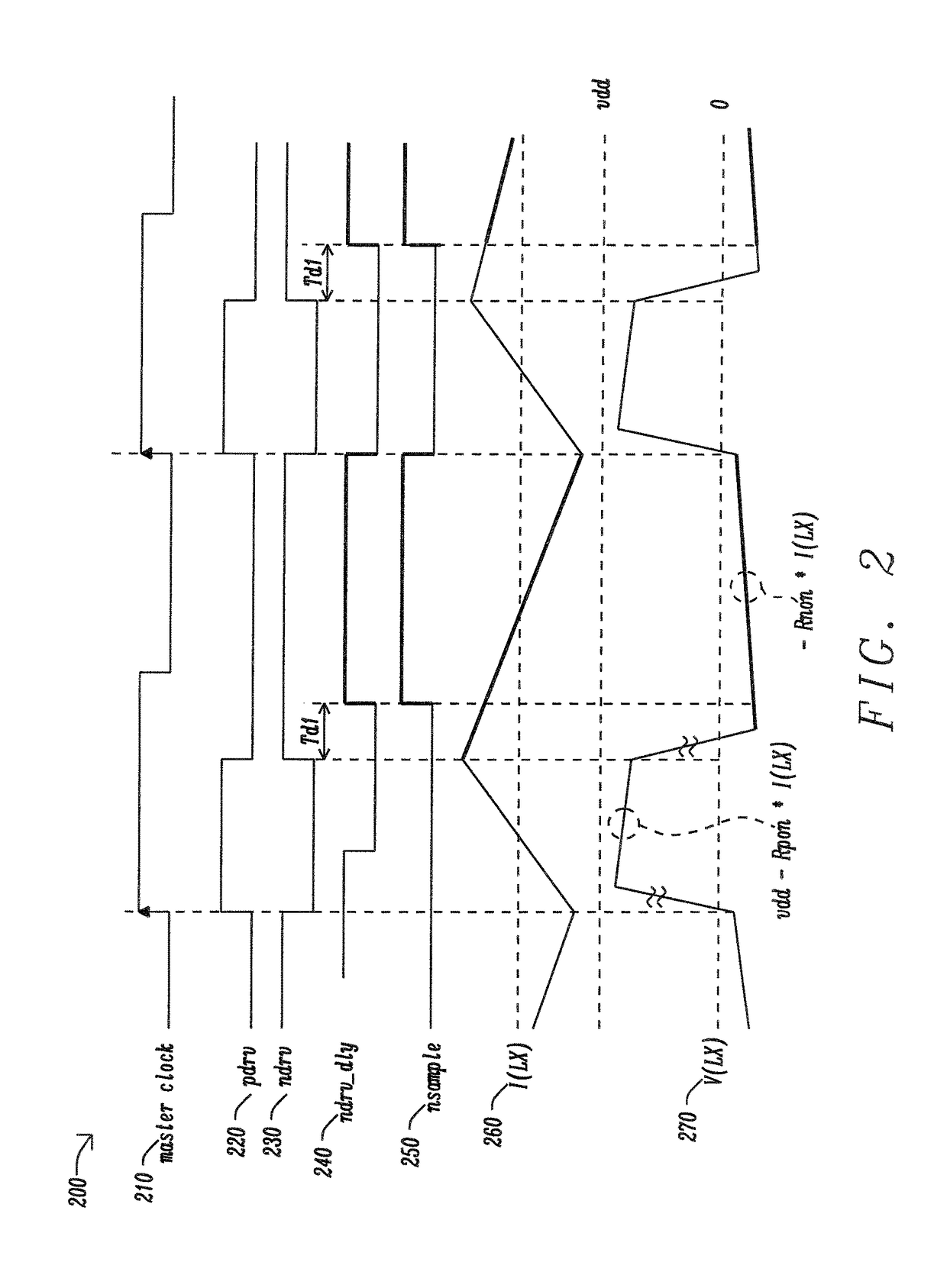
[0038]FIG. 3 is a circuit schematic in accordance with the disclosure. FIG. 3 shows a block diagram of the invention. The Master clock 302 is delayed by the delay element Delay Td2303 and used for PWM controller 305. Sampling signal nsample is generated in the Sampling timing generator 370. It starts the first delay element Delay Td1377 after ndrv is activated. Its end is the second delay element Delay Td2303 earlier than ndrv, because nsample is reset by Master clock 302 but signal ndrv 312 is reset by delayed clock. This sampling timing generator is logic circuit and various kinds of implementations are possible. The necessary elements are as follows: (1) the first flip-flop which is set by rise of master clock and reset when sampling signal is inactive; (2) the second flip-flop of which output is sampling signal which is set by delayed ndrv, and reset when ndrv is inactive or when first flip-flop is active, (3) and a delay which is generated delayed ndrv from ndrv.

[0039]FIG. 3 sh...

second embodiment

[0045]FIG. 5 is a circuit schematic in accordance with the disclosure. FIG. 5 shows average output current monitor implemented in a buck regulator. The essential elements in this implementation for the sampling timing generator are: (1) Sampling timing is generated as AND of ndrv, ndrv_dly and mask signal; (2) Ndrv_dly is delay of ndrv, and (3) a mask signal is inactive only from master clock's rise to delayed clock's rise. The buck 500 is composed of PWM controller 505 and output stage 530. Output current monitor is sampling timing generator 570, sampler and sense circuit 550. The PWM controller 505 has an input signal from Master clock signal 502, followed by the second delay element Delay Td2503, and a second input signal from Error amplifier 515. The Error amplifier 515 has two inputs, with a vout signal 520 and reference signal vref 525. The PWM controller 505 generates two output signals pdrv 511 and ndrv 512. The Output stage 530 contains PMOS 535 and pre-drive inverter 540, ...


PUM


Abstract

A circuit and method for providing an improved current monitoring circuit for a switching regulator. A circuit providing switching regulation with an improved current monitor, comprising a pulse width modulation (PWM) controller configured to provide P- and N-drive signals, an output stage connected to said PWM controller and configured to provide switching, comprising a high-side and low-side transistor, driven by said P- and N-drive signals, respectively, a sense circuit configured to provide output current sensing from the output stage during a sampling period when the N-drive signal is active, and a sampling timing generator configured to provide a an n-sampling signal, nsample, to the sense circuit, wherein a start of the n-sampling signal is delayed by a first delay after the sampling period and the n-sampling signal is ended prior to an end of the sampling period by a second delay.

Description

RELATED PATENT APPLICATION[0001]This application is related to Ser. No. 14 / 550,921, filed on Nov. 22, 2014, which is assigned to a common assignee, and which is herein incorporated by reference in its entirety.BACKGROUND[0002]Field[0003]The disclosure relates generally to a voltage regulator and, more particularly, to output current monitoring circuit thereof.[0004]Description of the Related Art[0005]Voltage regulation is important where circuits are sensitive to transients, noise and other types of disturbances. The control of the regulated voltage over variations in both semiconductor process variation, and temperature is key to many applications. Additionally, power consumption is also a key design requirement.[0006]In a recent power management integrated circuit (PMIC), precise output monitoring of a buck is required for more efficient power management of processors. Average output current is sensed and digitized, and used for controlling processors.[0007]FIG. 1 shows average ou...

Claims


Application Information

Patent Timeline
Patent Type & Authority Patents(United States)
IPC IPC(8): H02M3/158H03K5/1536H02M3/156H02M1/00
CPCH02M3/158H02M3/156H03K5/1536H02M2001/0009H02M3/1588H02M1/0009
Inventor OZAWA, SEIICHI
Owner DIALOG SEMICON UK
Why Eureka
Try Eureka